Hardware Hacking with a Raspberry Pi - Configuring the PiFex
July 2024
Introduction
In our last post, we released the PiFex, a low-cost tool that we designed to help introduce people to hardware hacking using the Raspberry Pi. In that blog post, we reviewed the hardware on the PiFex and an example of reverse engineering a JTAG TAP on an unknown device. In that post, we mostly reviewed the hardware; in today’s post, we will review how to configure a Raspberry Pi image for hardware reverse engineering.
Background: Why a Pi?
If you want to get straight to setting up an image, feel free to head to the next section. However, if you want to learn a little more about why we opt for teaching hardware hacking concepts using the Pi, please continue reading.
Like many disciplines, there are an infinite amount of hardware and software tools that you can use when beginning your journey into hardware reverse engineering. For many people, the first tool they choose to start with will depend on their professional background or personal interests; for example, perhaps you’re an FPGA engineer by day, and you might be able to whip up some Verilog in 10 minutes to communicate with an SPI flash. Maybe you’re an embedded engineer, and the easiest way for you to interact with a UART is by writing firmware for an STM32. Maybe you are following one of my old tutorials and are using a Bus Pirate or ESP32. Luckily for us, in all of these cases you are right!
There is no one tool to rule them all regarding reverse engineering embedded systems. Often, it simply boils down to the features of the system you are targeting and your personal preferences.
So why this long rant? Well, for one, I always get emails about how much easier it would be if I used __ when I publish a post on reverse engineering hardware, and I wanted to get ahead of that. But I also wanted to clarify to those reading this that it is much less about the tool you are using for hardware reversing and more about how much you understand the underlying protocol. We spend a lot of time focusing on this in our training, and I have found this approach to best serve students after they leave the classroom.
I opted to use a Pi for several reasons:
- It has most of the commodity interfaces that we run into when looking at COTS (commercial off-the-shelf) hardware, such as SPI, I2C, UART, JTAG, and SWD
- These can be interacted with using the student’s language of choice (Python, Rust, C, Go, etc.)
- It has a large community of supporters, and therefore troubleshooting is a little more streamlined
- It runs Linux!
- This means that the tools and techniques that we use in class apply to other embedded Linux SBCs such as the BeagleBone Black, Orange Pi, etc
One of my favorite things about using an embedded Linux platform for basic hardware hacking is that all of the interfaces that we are interested in are often exposed through /dev/ .This means that we can write Python, Rust, C/C++ or even bash to interface with these peripherals. In the next section, we’ll talk about how to configure a Raspberry Pi to interact with these various interfaces.
Setting up an Image
We will be basing our image on the latest Raspbian release; you can acquire and flash this to your SD card using the latest version of the Raspberry Pi Imager tool found here.
Step 1: Download Raspbian / Raspberry Pi Imager
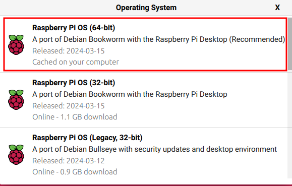
After downloading the Raspberry Pi imager tool, execute it and click the CHOOSE OS button from here select the highlighted Raspbian version shown below:
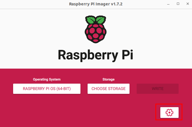
Insert the SD card you wish to image into your computer. Next, select CHOOSE STORAGE and select the SD card you wish to image.
Before we begin the imaging process, click the gear icon highlighted below to open additional settings:
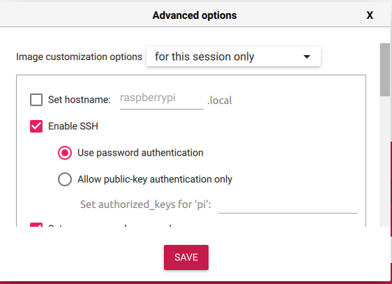
Using this menu, select Enable SSH as shown below and configure the desired username and password and the wireless network information (assuming you want your Pi to be networked).
Finally, write this image to your SD card using the WRITE button.
After imaging, insert the SD card into your Pi and power it on.
Step 2: USB Ethernet Gadget Setup
The Raspberry Pi features an “On the Go” (OTG) USB controller. This means the USB controller can act as a USB device or host. We can utilize this to have the Pi present specific USB devices to the host computer plugged into it. We will use it to present an Ethernet adapter over USB, allowing us to SSH into the Pi via USB.
Note: The following instructions assume you have console access to your Raspberry Pi. If you are running Linux, you can insert the SD card into your host computer and manually edit these.
We will configure the Raspberry Pi to present a USB Ethernet gadget on boot. This will allow us to SSH into the Raspberry PI using the Ethernet adapter presented over USB. This is all configured using FunctionFS; you can learn more about that here.
The first thing that we need to do is enable the OTG controller,we can do this by adding the following to /boot/config.txt
# PiFex Ethernet Gadget
dtoverlay=dwc2
After enabling the DWC2 gadget driver, we need to specify which USB gadget we want to be loaded at startup. To do that, add the following to /boot/cmdline.txt
modules-load=dwc2,g_ether
Next, you can configure your gadget however you’d like. For instance, if you want the gadget to always have the same IP address, you can add the following to /etc/network/interfaces.
allow-hotplug usb0
iface usb0 inet static
        address 192.168.7.2
        netmask 255.255.255.0
        network 192.168.7.0
        broadcast 192.168.7.255
        gateway 192.168.7.1
This will allow you to ssh into your Pi over USB via the Ethernet gadget at 192.168.7.2, which is much more convenient than guessing what IP it has obtained on your network or requiring an additional monitor, keyboard, and mouse.
Upon a reboot, you should see an Ethernet interface presented over USB. If you are running Windows and you see an unknown device in the device manager, install the drivers using the example here.
Note: When you power on the Pi, it will present an Ethernet interface to the host computer over USB. You will need to statically configure the IP of this device to access the Pi. This guide has instructions for how to do this across multiple operating systems.
With the Ethernet gadget present, you can SSH into the Pi over USB using the details you specified in the previous step. When you log into the Pi, you should now see a usb0 interface in the results of ip link list:
pi@voidstar:~ $ ip link list
1: lo: <LOOPBACK,UP,LOWER_UP> mtu 65536 qdisc noqueue state UNKNOWN mode DEFAULT group default qlen 1000
    link/loopback 00:00:00:00:00:00 brd 00:00:00:00:00:00
2: eth0: <NO-CARRIER,BROADCAST,MULTICAST,UP> mtu 1500 qdisc mq state DOWN mode DEFAULT group default qlen 1000
    link/ether e4:5f:01:b5:68:2e brd ff:ff:ff:ff:ff:ff
3: usb0: <NO-CARRIER,BROADCAST,MULTICAST,UP> mtu 1500 qdisc pfifo_fast state DOWN mode DEFAULT group default qlen 1000
    link/ether 76:db:82:b8:68:b1 brd ff:ff:ff:ff:ff:ff
4: wlan0: <BROADCAST,MULTICAST,UP,LOWER_UP> mtu 1500 qdisc pfifo_fast state UP mode DORMANT group default qlen 1000
    link/ether e4:5f:01:b5:68:30 brd ff:ff:ff:ff:ff:ff
If you don’t see that in your output, check dmesg for any logs or errors related to the USB controller or power consumption. Often, laptop USB ports can not provide appropriate power to the Pi when it presents a USB gadget, causing it to fail to enumerate. Also, make sure that your cable is not just power only. You would be surprised how many USB C cables I have come across that only have power and no data lines.
Now that we can easily access our PiFex over USB, let’s examine some common tools that we’ll use in future blog posts.
Step 3: Software Dependencies and Tools
At its core, the goal of the PiFex is to easily streamline access to some of the commodity interfaces on the Raspberry Pi. We use the Pi for training and hardware assessments we perform for clients. When we conduct a hardware security training we focus on using Open-Source tooling and libraries to ensure that students are not tied to a specific hardware platform in the future. The goal of training, after all, is to teach the underlying concepts instead of the specifics of the tools used.
Below are a few common tools that can be used to interface with the SPI, UART, JTAG, SWD and I2C interfaces
flashrom- This tool is used to interact with SPI flash chips, something you will come across frequently when looking at cots hardwarei2c-utils- These tools are used to interract with I2C devicesscreen/minicom- Used to interact with the UART interfaces on the PiOpenOCD- Used to interface with JTAG and SWDUrJTAG- Used to manually interact with a JTAG TAP
The following command can be used to install basic utilities and open-source tools that can be used to interact with hardware peripherals on the Raspberry Pi:
sudo apt-get install build-essential vim tmux git screen flashrom i2c-tools can-utils minicom cmake ipython3 python3-pip urjtag binwalk
Now that we have many of our common tools installed, let’s discuss how to instrument and access the OLED screen.
OLED Testing and Usage
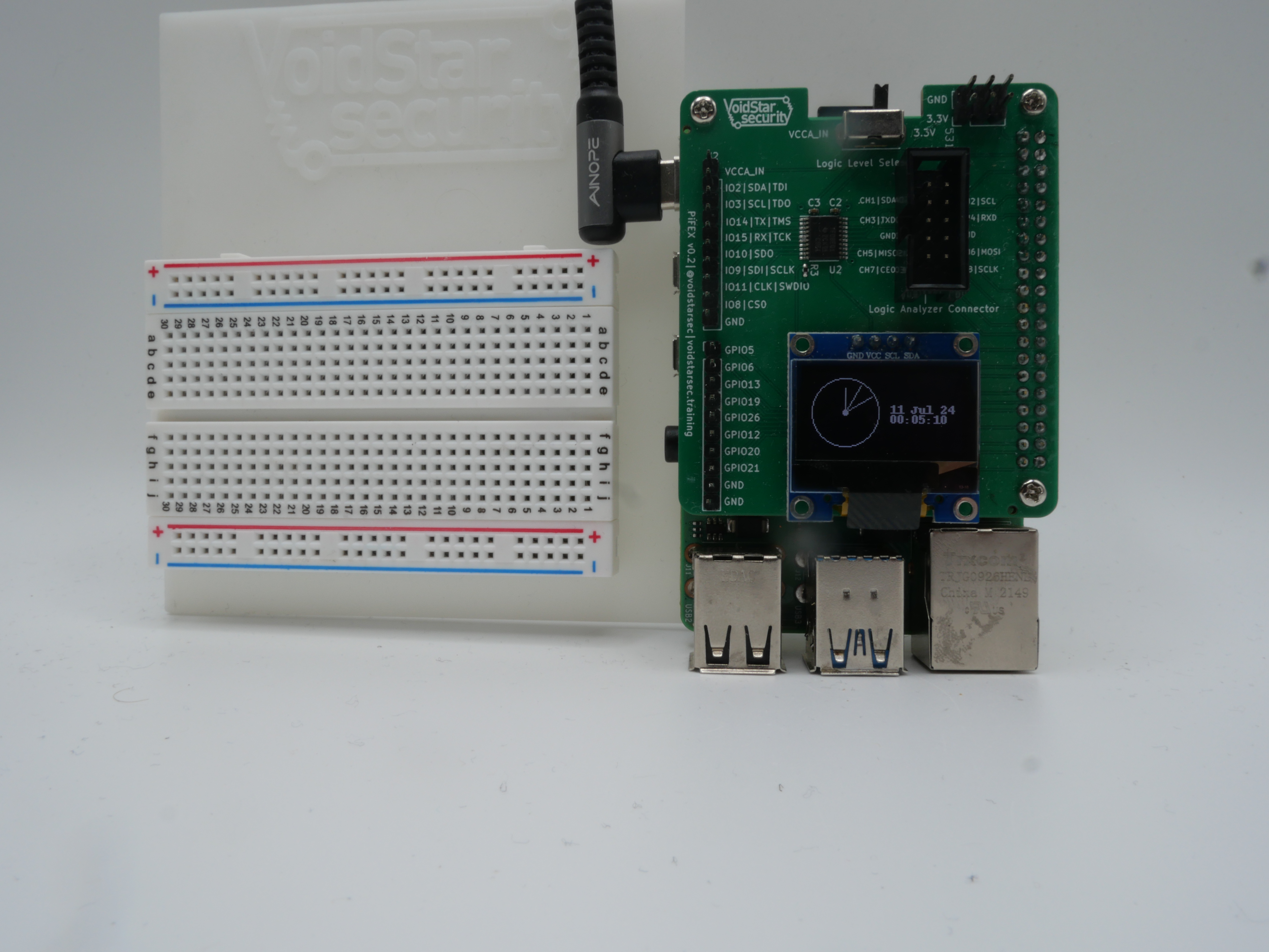
The PiFex contains a 128x64 I2C OLED screen. This allows users to display custom images, statistics or messages:
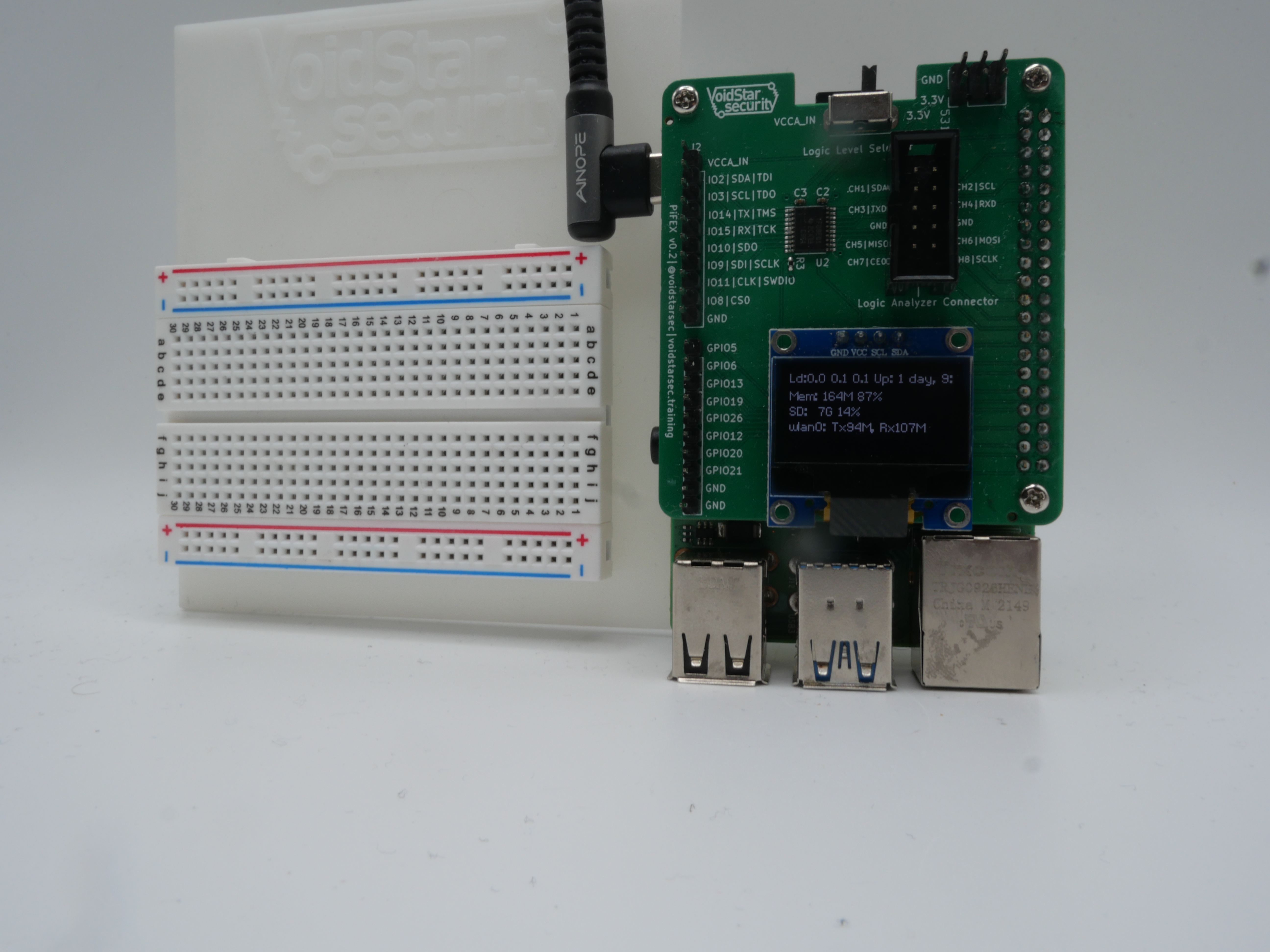
The I2C OLED is located at address 0x3C on the PiFex using the I2C peripheral located on GPIO22 and GPIO23. The pin location for the standard pinout can be seen below:
J8:
   3V3  (1) (2)  5V
 GPIO2  (3) (4)  5V
 GPIO3  (5) (6)  GND
 GPIO4  (7) (8)  GPIO14
   GND  (9) (10) GPIO15
GPIO17 (11) (12) GPIO18
GPIO27 (13) (14) GND
GPIO22 (15) (16) GPIO23
   3V3 (17) (18) GPIO24
GPIO10 (19) (20) GND
 GPIO9 (21) (22) GPIO25
GPIO11 (23) (24) GPIO8
   GND (25) (26) GPIO7
 GPIO0 (27) (28) GPIO1
 GPIO5 (29) (30) GND
 GPIO6 (31) (32) GPIO12
GPIO13 (33) (34) GND
GPIO19 (35) (36) GPIO16
GPIO26 (37) (38) GPIO20
   GND (39) (40) GPIO21
Note: This was captured with the pinout command line utility on the Raspberry Pi; this, paired with raspi-gpio, can be very helpful when first learning how to use the various peripherals on the Pi.
This is not the standard I2C peripheral that we normally use on the Pi, so to enable it we will have to configure an additional device tree overlay. To do this, add the following line to /boot/config.txt
# PiFex Enable I2C Screen
dtoverlay=i2c-gpio,bus=3,i2c_gpio_sda=22,i2c_gpio_scl=23
This line tells the kernel to do the following:
- Load the
i2c-gpiodevice tree overlay - Label the resulting bus as bus
3- This means it will show up in
/dev/asi2c-3
- This means it will show up in
- Use the IO pins
22forSDAand23forSCL
After editing this file, reboot your Raspberry Pi. After rebooting the Pi, we should be able to use i2cdetect to detect our OLED screen; you can test this as follows:
pi@voidstar:~ $ i2cdetect -y 3
     0  1  2  3  4  5  6  7  8  9  a  b  c  d  e  f
00:                         -- -- -- -- -- -- -- --
10: -- -- -- -- -- -- -- -- -- -- -- -- -- -- -- --
20: -- -- -- -- -- -- -- -- -- -- -- -- -- -- -- --
30: -- -- -- -- -- -- -- -- -- -- -- -- 3c -- -- --
40: -- -- -- -- -- -- -- -- -- -- -- -- -- -- -- --
50: -- -- -- -- -- -- -- -- -- -- -- -- -- -- -- --
60: -- -- -- -- -- -- -- -- -- -- -- -- -- -- -- --
70: -- -- -- -- -- -- -- --
Note: If you’d like to learn more about i2cdetect and the other I2C utils, see our blog post here.
Now, we can interact with the screen using the Luma OLED libraries; these can be installed as shown below:
pip3 install luma.oled
With Luma installed, we can download the examples and test them out.
git clone https://github.com/rm-hull/luma.examples.git
cd luma.examples
sudo -H pip install -e .
Note that if you are using the examples provided by Luma, you will have to specify the --i2c-port field when running the examples. This value will be the bus number that you specified in the previous section (3 if you have been following along!)
python3 clock.py --i2c-port 3
python3 sys_info_extended.py --i2c-port 3
With our screen tested and working, lets move on to enabling some of the common peripherals that are exposed via the PiFex headers.
Enabling Peripherals
When working with (or reverse engineering) an embedded Linux device, it is important to be familiar with the concept of device trees. Device trees are used to describe the underlying hardware to the kernel, letting the operating system know what hardware is present and how to interface with it. We can use compiled device tree source files (device tree blobs) to modify the state of the various peripherals on the Raspberry Pi.
There are a number of ways to set up and configure the peripherals on the Raspberry Pi from user space. A few of them can be seen in the list below:
raspi-configraspi-gpiodtoverlay- Manual configuration in
/boot/config.txt
All of these tools manipulate and modify the device tree overlay in use by the Pi, allowing various peripherals to be enabled and configured. For this example we will use the most user-friendly option, raspi-config. We will use raspi-config to enable the UART, SPI and I2C interfaces exposed via the PiFex headers.
We will start with the SPI interface, begin by launching raspi-config as root from the command line:
sudo raspi-config
This will cause the following ncurses window to appear:
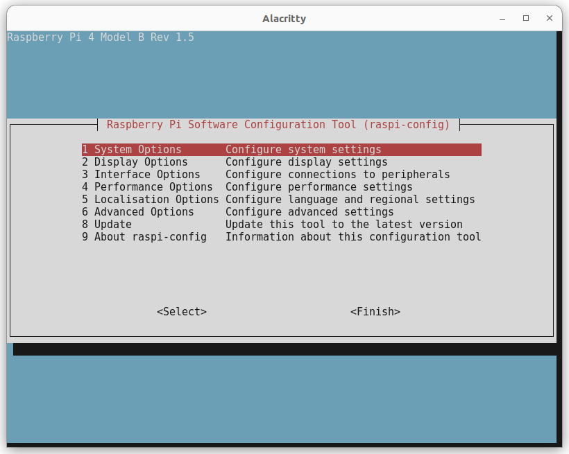
From the first window, select option 3, Interface Options, this will open the following window:
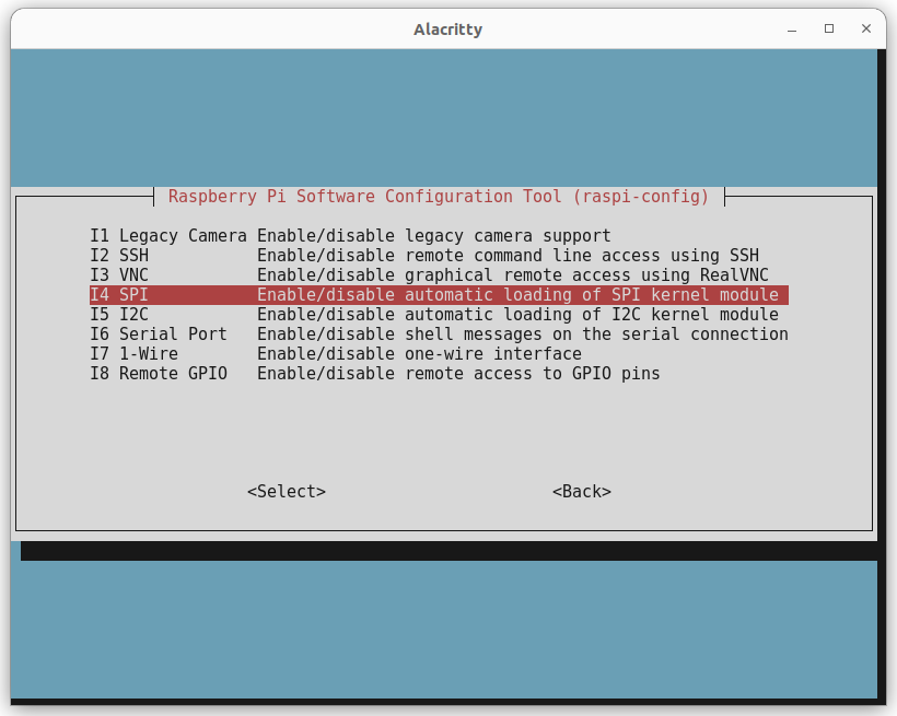
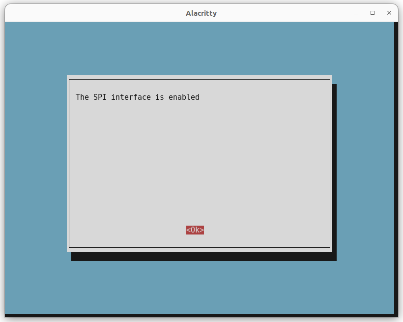
In this example we will enable the SPI interface, by selecting option I4 the interface will be enabled and confirmed with the following screen.
Next, perform the same steps for I2C and UART, and make sure that a console is not enabled on boot. After this, reboot your pi and you should see the following interfaces in /dev/
pi@voidstar:~/pifex/nes-demo $ ls /dev/ | grep -E 'i2c|S0|spi'
i2c-1 <-- This is the standard I2C interface (exposed via Pifex Header)
i2c-20
i2c-21
i2c-3 <-- This is our screen
spidev0.0 <-- This is the SPI interface (exposed via PiFex header)
spidev0.1
ttyS0 <-- This is the UART interface (exposed via PiFex header)
At this point, we have enabled some of the common interfaces used for hardware hacking and reverse engineering. Next, we will talk about how to set up and install Jupyter notebooks, along with an example notebook from our previous JTAG post.
Step 4: Jupyter Notebook Setup and Usage
When giving a training or explaining a new topic or tool to a client, Jupyter notebooks are an excellent way to teach new concepts and provide demonstrations. We leverage these in our training and in assessments and blog posts. In this section we will review how to install and run jupyter-lab on the Raspberry Pi.
The Jupyter-Lab package can be installed via pip as shown below:
pip3 install jupyterlab
A jupyter instance can be started by running jupyter-lab from the directory containing your notebooks. For example, to access the JTAG notebook that we used in the last blog post you can run the following:
git clone https://github.com/voidstarsec/pifex-sw
cd pifex-sw/notebooks
jupyter-lab . --ip 0.0.0.0
Now, the Jupyter Notebooks can be accessed at 192.168.7.2:8888. In our pifex-sw repository, you can find examples of a JTAG notebook that we developed for the previous blog post. We will add more notebooks and examples with corresponding blog posts.
Conclusion and Kit Updates
This post has covered how to set up a Raspberry Pi for basic hardware hacking. We reviewed how to configure a USB Ethernet gadget to allow for SSH over USB, common packages and tools used for hardware reverse engineering, how to interact with the OLED screen on the PiFex, and how to configure various interfaces on the Raspberry Pi.
Notebooks and setup scripts can be found in the GitHub repository here.
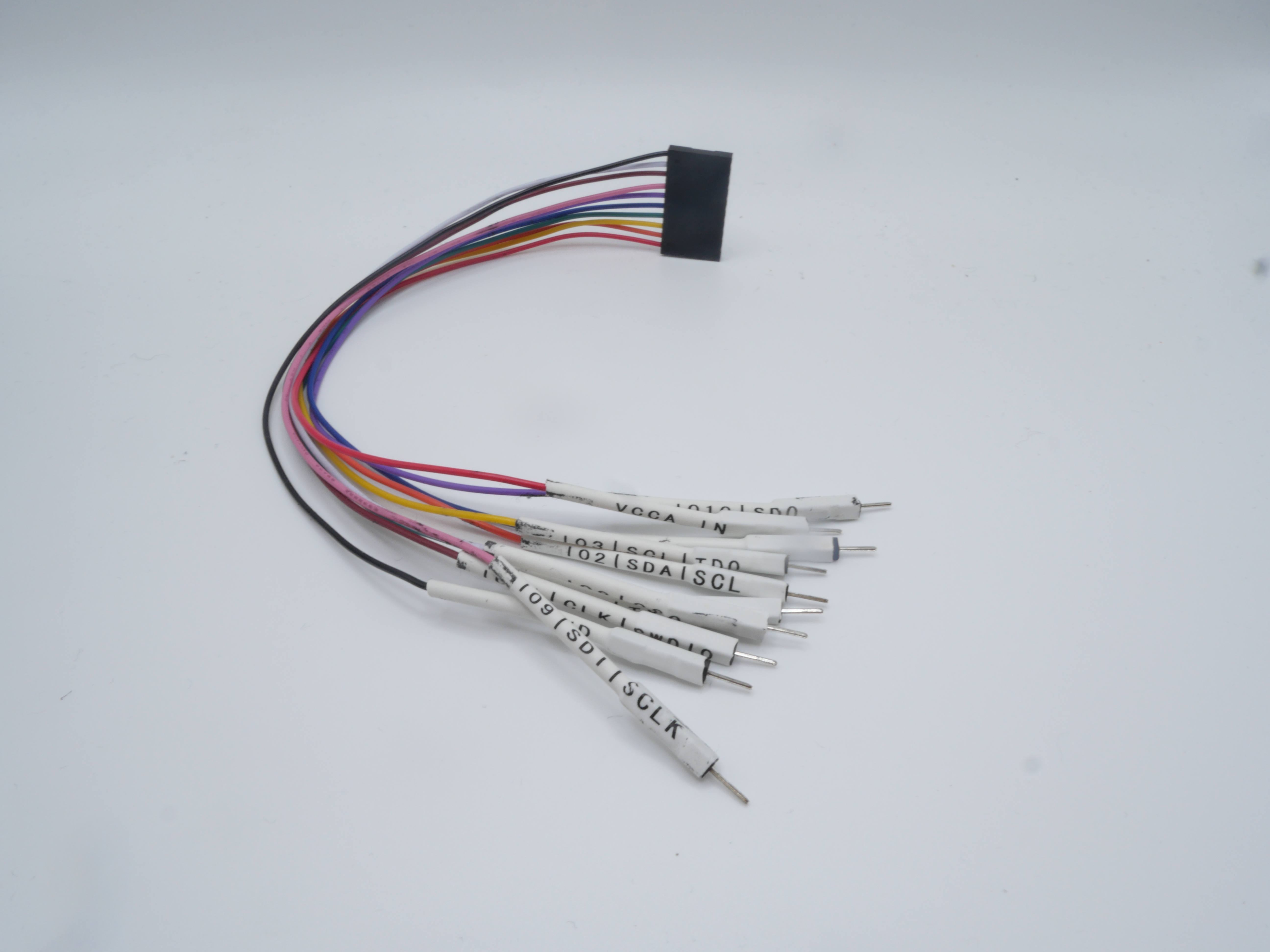
In addition to these software instructions, we have also designed a custom cable harness with labeled jumper wires that can be seen in the image below:
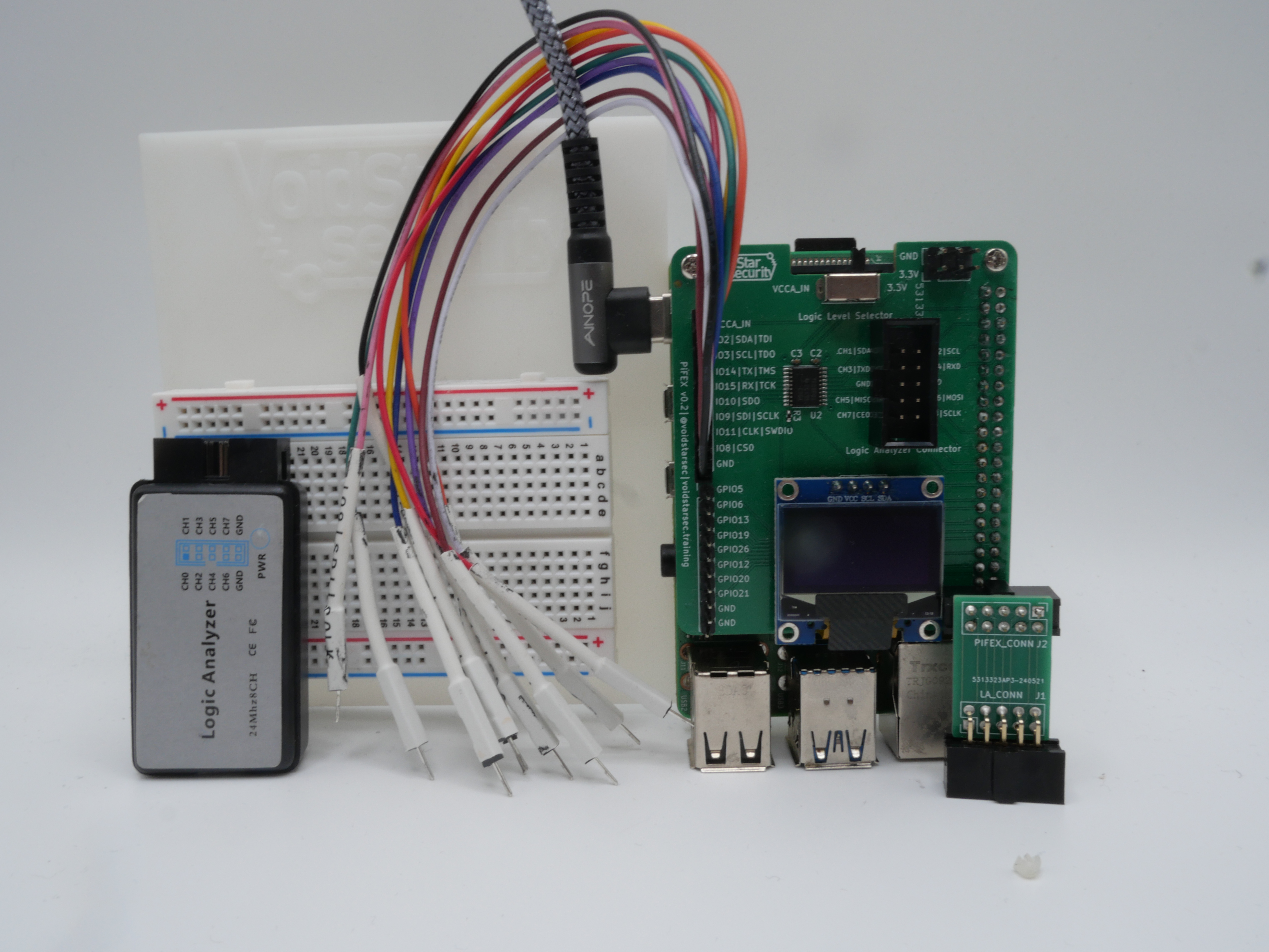
We also have developed a basic baseplate for the Raspberry Pi and a small breadboard that we use for our hardware hacking trainings:

To purchase a full PiFex kit, including a provisioned SD card, check out our store here.
If you’re interested in a hardware security training at your organization, please don’t hesitate to contact us.
If you want to stay up to date on the official releases, new courses and blog posts sign up for our mailing list here.
Lastly, as conference season is well underway, I wanted to highlight a new conference that is being put on by an awesome group of researchers: RSTCON. This conference is focused on cutting-edge research, exploitation, and tradecraft in the logistics, energy, and manufacturing industries. The speaker lineup looks incredible and this is a conference that I plan on attending regularly!
If you’re looking for a discounted ticket, you can use the promo code wrongbaud for a 10% discount
Thank you for reading!