Intro to Embedded RE: UART Discovery and Firmware Extraction via UBoot
Previous Entries
- Part 1: Tools / Series Overview
- Part 2: Building a Development Environment for Ghidra
Overview
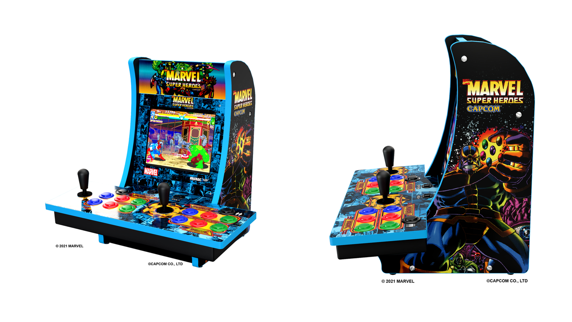
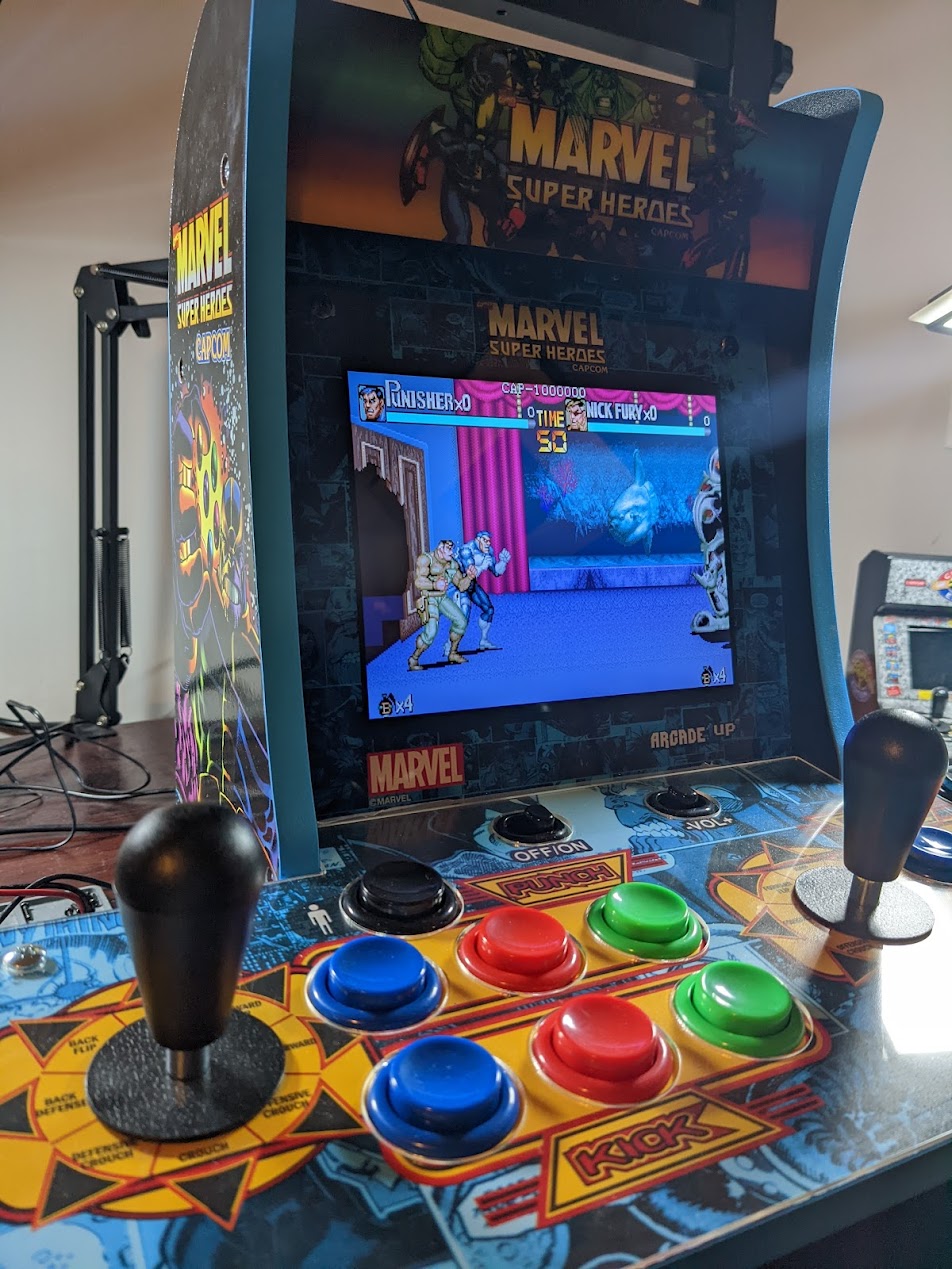
Welcome to the third post in our Intro to Embedded RE series. This post will be focused on UART, UBoot, and USB using the Arcade 1UP Marvel countertop cabinet as a target. The Arcade 1Up series of cabinets are an affordable way to set up an arcade in your home. Since the launch of these cabinets, there have been plenty of mods that demonstrate how to replace the internal components of the cabinet to run generic MAME software. This post will look at the stock hardware and determine how to extract the firmware.
Goals
With this post, we will review the following:
- Performing a teardown of an embedded system
- Component identification via IC markings
- Measuring header voltages with a multimeter
- Logic analyzer usage and setup
- UBoot analysis and review
- Scripting UBoot interactions with depthcharge
This blog entry aims to familiarize readers with locating an active UART on a target system, how to approach a UBoot console, and ultimately how to leverage both of these components to extract the flash memory from our target. After reading this, readers will be familiar with the screen utility the depthcharge python3 libraries.
Hardware Overview
When looking at a new target, one of the first tasks is to review the available interfaces. In the case of this arcade cabinet, the available interfaces are relatively slim at first glance. Users interact with this device through the joystick/buttons and a USB port on the side of the cabinet. There seems to be little information regarding the USB port on the side of the cabinet. Note that even in the pictures on the site, there is no USB port. However, there is a USB device port on the side of the cabinet meant to provide external controller support. On the opposite side, we have a standard headphone jack. These two peripherals behave as expected, the USB port can be used to attach an external controller, and the headphone jack works as advertised.
RE Tip: On some older mobile phones, it was possible to configure the audio jack to present a serial terminal on boot. More information on this can be found here. Unfortunately, no such modifications worked on this platform.
With the current knowledge, there does not seem to be much more we can explore externally. So, next, we will open the cabinet up and see what is inside!
Cabinet Teardown
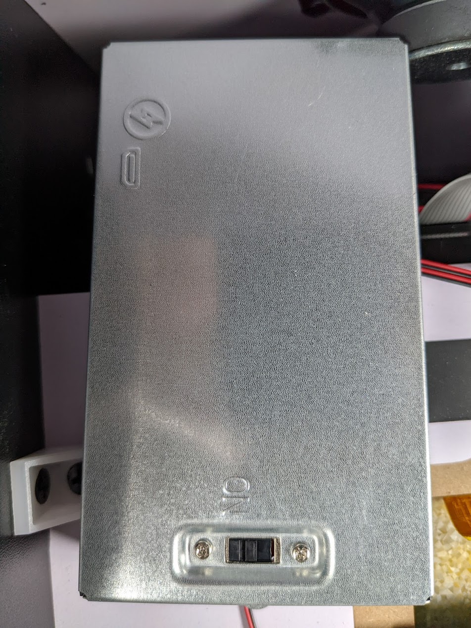
The cabinet is pretty empty, except for a metal housing attached to the screen.
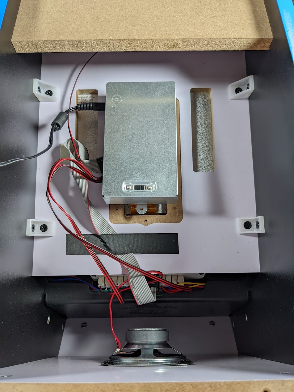
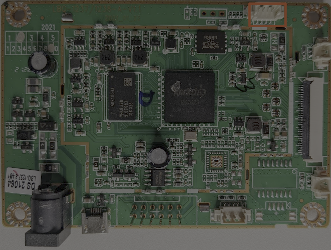
Beneath the metal enclosure, we find the main PCB for our cabinet; after gently removing an additional metal shield, we see the following.
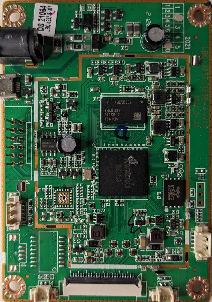
When looking at a PCB such as this for the first time, we first want to take note of any part numbers and see if we can find any datasheets. The first component that stands out to me has been highlighted in blue.
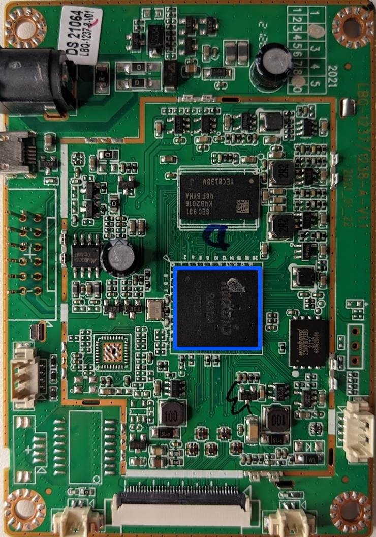
This part reads Rockchip RK3128 if we search this part number online, we find a large amount of information - see the information below that was pulled from the Rockchip wiki
- CPU
- Quad-core ARM Cortex-A7MP Core processor, a high-performance, low-power and cached application processor
- Full implementation of the ARM architecture v7-A instruction set, ARM Neon Advanced SIMD (single instruction, multiple data) support for accelerated media and signal processing computation
- GPU
- ARM Mali400 MP2
- High performance OpenGL ES1.1 and 2.0, OpenVG1.1 etc
- Memory
- 8KB internal SRAM
- Dynamic Memory Interface (DDR3/DDR3L/LPDDR2): Compatible with JEDEC standard DDR3-1066/DDR3L-1066/LPDDR2-800 SDRAM. Supports 32 Bits data width, 2 ranks (chip selects), totally 2GB (max) address space.
- Nand Flash Interface: Support 8bits async/toggle/syncnandflash, up to 4 banks. 16bits, 24bits, 40bits, 60bits hardware ECC
- eMMC Interface: Compatible with standard eMMC interface, Support MMC4.5 protocol
- Video
- Real-time video decoder of MPEG-1, MPEG-2, MPEG-4,H.263, H.264, H.265, VC-1, VP8, MVC
- Audio
- I2S/PCM with 8 channels: Up to 8 channels (8xTX, 2xRX). Audio resolution from 16bits to 32bits. Sample rate up to 192KHz
- I2S/PCM with 2ch: Up to 2 channels (2xTX, 2xRX). Audio resolution from 16bits to 32bits. Sample rate up to 192KHz
- Connectivity
- SPI Controller: One on-chip SPI controller
- UART Controller: 3 on-chip UART controllers
- I2C controller: 4 on-chip I2C controllers
- USB Host2.0: Embedded 1 USB Host 2.0 interfaces
- USB OTG2.0: Compatible with USB OTG2.0 specification. Supports high-speed(480Mbps), full-speed(12Mbps) and low-speed(1.5Mbps) mode
From this description alone, we have learned much about our target processor. We now know the architecture and available peripherals and interfaces; these are useful to us as they may outline attack vectors in the future. It is important to remember that there is no such thing as too much information in this phase of the reverse engineering process. We want to learn as much about our target before attempting to interface with it.
Directly next to the CPU, we have another component highlighted in orange below.
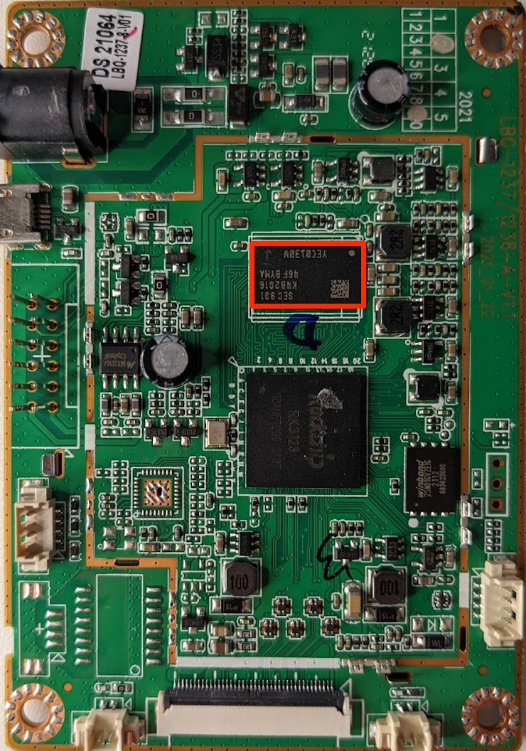
This component is marked SEC931 K4B2G1646F-BYMA, we are lucky and searching this part number results in this webpage from Samsung. The information on this page tells us that this is a 2GB DDR3 SDRAM chip. A datasheet can also be acquired from this page; it is always worth collecting datasheets when they are available when doing this kind of work. This chip is responsible for expanding the available memory to the CPU and providing a volatile memory source (RAM).
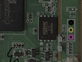
Thus far, we have identified what is likely the main CPU and the external RAM. However, we are still missing a type of non-volatile storage. So, next, let's examine the component highlighted in pink below.
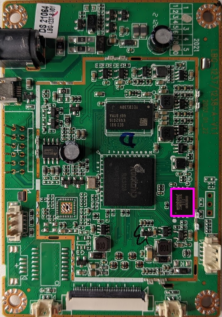
This component is labeled Winbond 25N01GVZEIG searching this part number leads us to this datasheet. This part is a 1G-bit serial SLC NAND flash memory chip. According to the datasheet, this chip utilizes the Serial Peripheral Interface and is compatible with voltage ranges between 2.6V and 3.3V. This chip likely houses the majority of the data in use by the cabinet and will be our main target for firmware extraction.
The last component is near the GPIO lines and is marked MIX2018A. This component is unlike the others that we have seen in that I could not find nearly as much information. However, based on a few sites, it would appear that this IC is an audio amplifier. The few mentions of this part that I was able to locate online all refer to it as such, so we will assume that is its function for the time being.
To recap the components that we've identified thus far, we have:
- Rockchip RK3128 ARM CPU
- Samsung SRAM Chip
- Winbond 1GBit NAND flash
- MIX2018A Audio Amplifier
Now that we have reviewed the integrated circuits on this board let's look at the connectors on the board and see what we can learn.
Connector Analysis
Now that we've documented the discrete components on the motherboard, we will attempt to identify the external connectors on the motherboard. First, we have the barrel connector; this connector is outlined in blue in the image below:
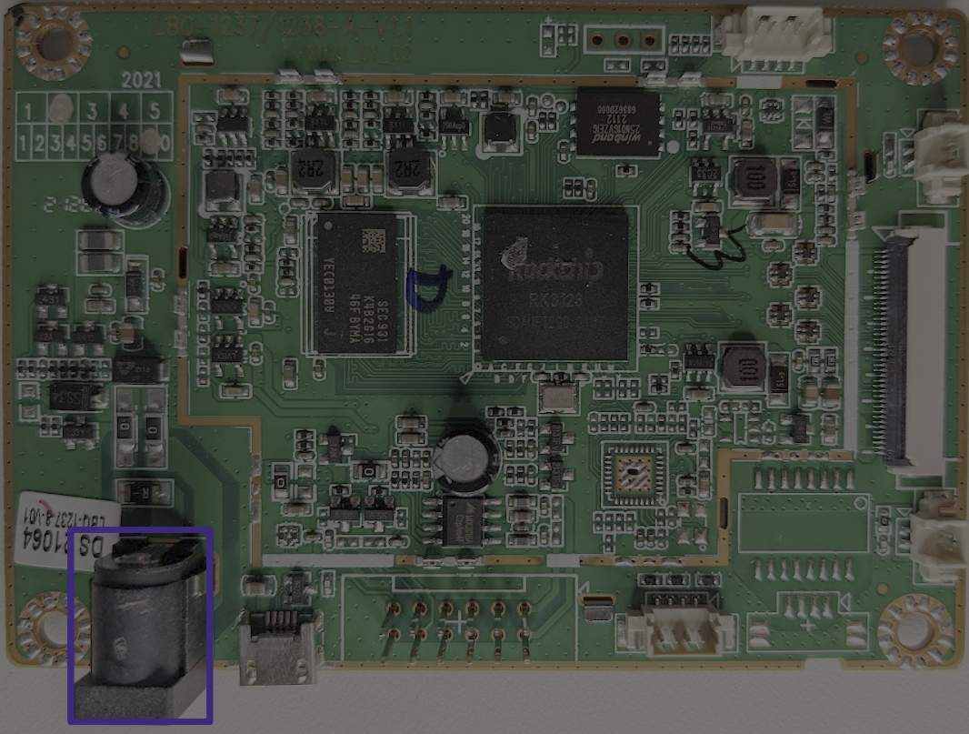
This connector is used to supply power to the cabinet.
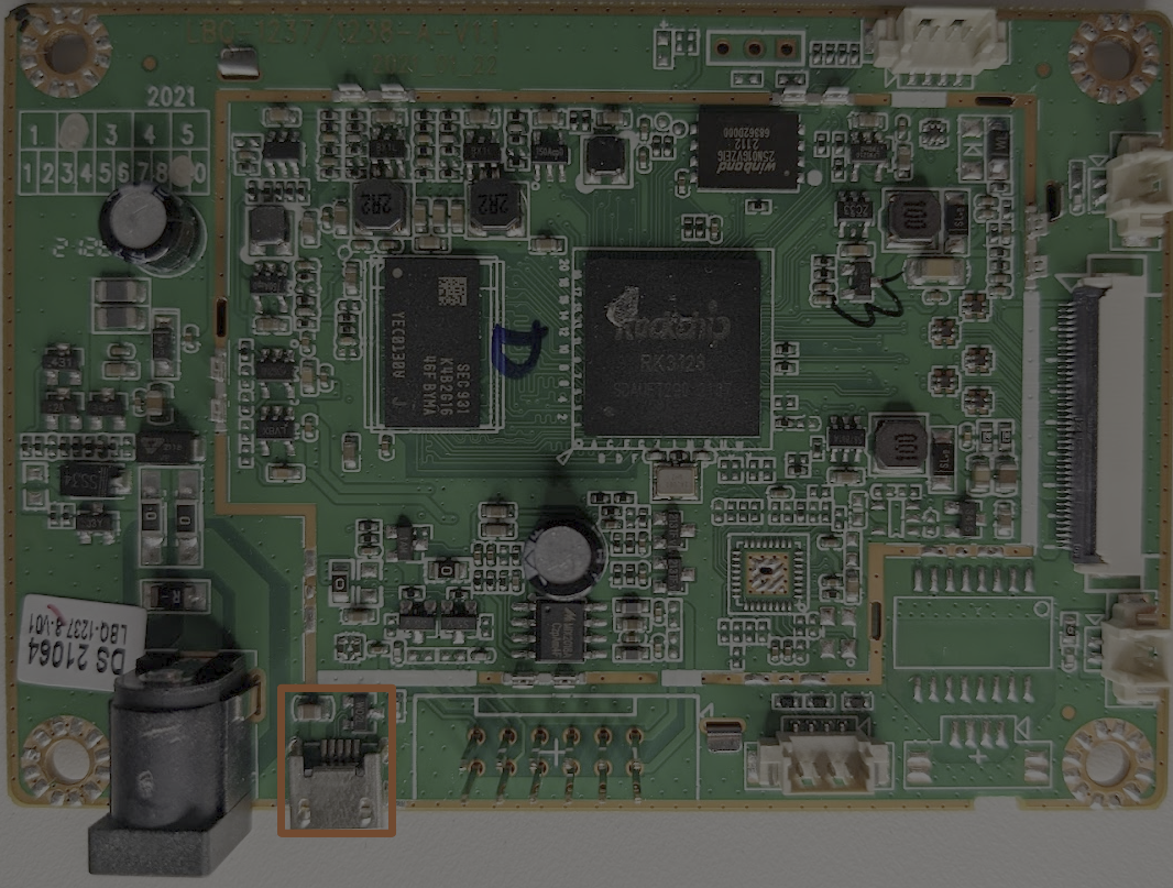
Directly to the right of the barrel connector, we have a micro-USB port. This should immediately raise eyebrows for two reasons:
- This is not a user-facing port
- This is not a USB host port; this is a micro port, indicative of a USB device or possibly an OTG (on the go) controller
Continuing to the right, we have two rows of header pins. These were connected via the grey ribbon cable shown in the earlier images. This connector goes to a separate control board and is used to handle the joysticks/buttons.
After our control panel connector, there is another four-pin connector. With this connector, it's not quite as obvious where it leads. For example, this connector could lead to the USB connector or the headphone jack. We can try to determine this with the multimeter using a continuity test. A continuity test will check if current can flow between the two probes and is usually indicated with one of the following symbols on your multimeter:

We can use this model to test if two components are connected. I inserted a 3/4 headphone cable into the headphone jack and held the probe to one of the metal rings to test this. Using the other probe, I touched each point of the four-pin connector, and on one of the lines, the multimeter let out a loud beep, letting us know a connection exists between these two points. Each of the three pins coincided with a ring on the audio connector; this is our audio jack!
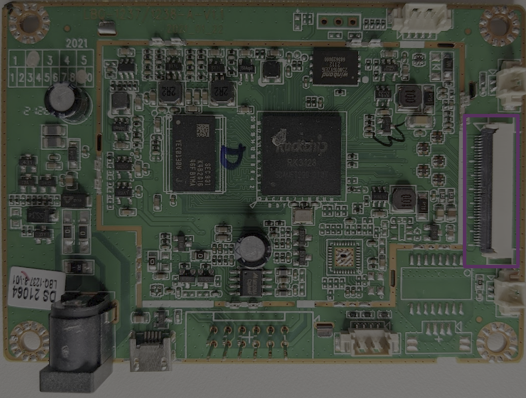
Next, we have the connector for the display:
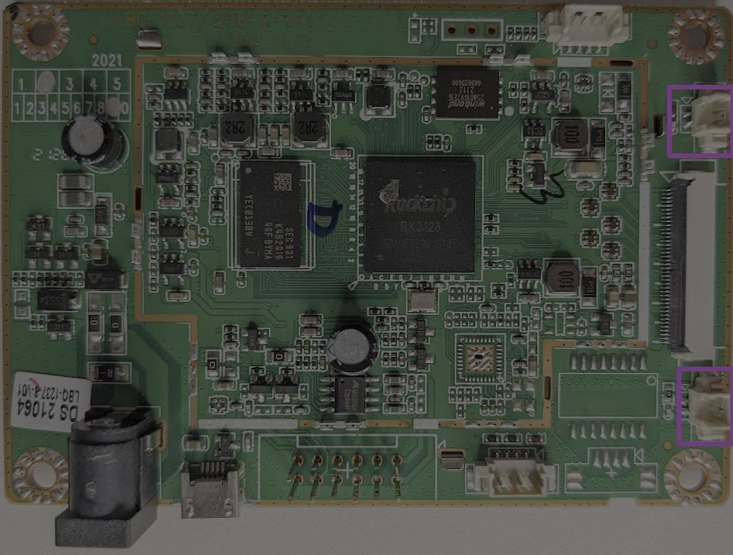
Near the display, we have two two-pin connectors, the one in the lower right-hand corner is used t power the backlight for the marquee, and the other goes to an on/off switch that resides on the outside of the metal housing.
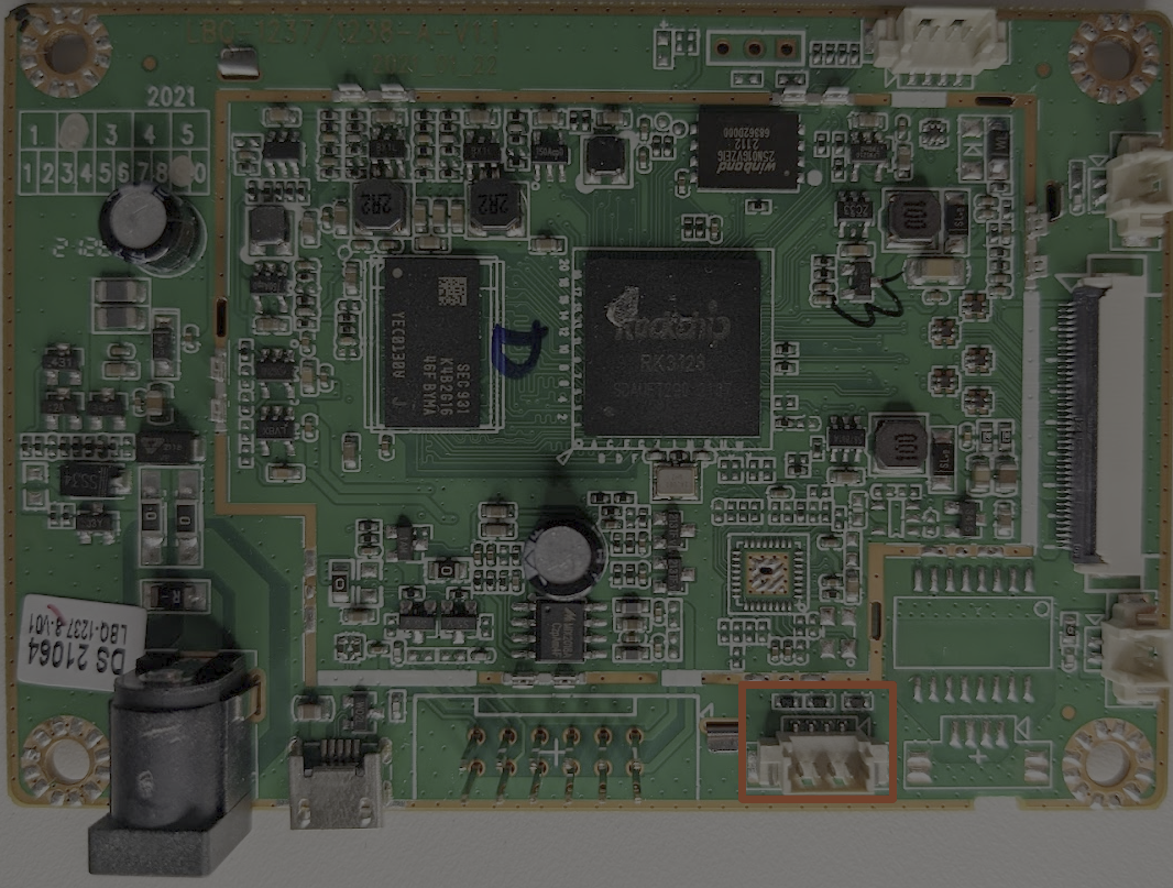
The following connector looks similar to the audio connector; it is a four-pin connector whose cables route to the control panel. There is only one other interface that we've not yet accounted for, and that is the USB connector on the side of the cabinet. If we set our multimeters to continuity mode and test the pins of this connector against the USB connector on the side of the cabinet, we find that they are indeed connected. This is our external USB connector.
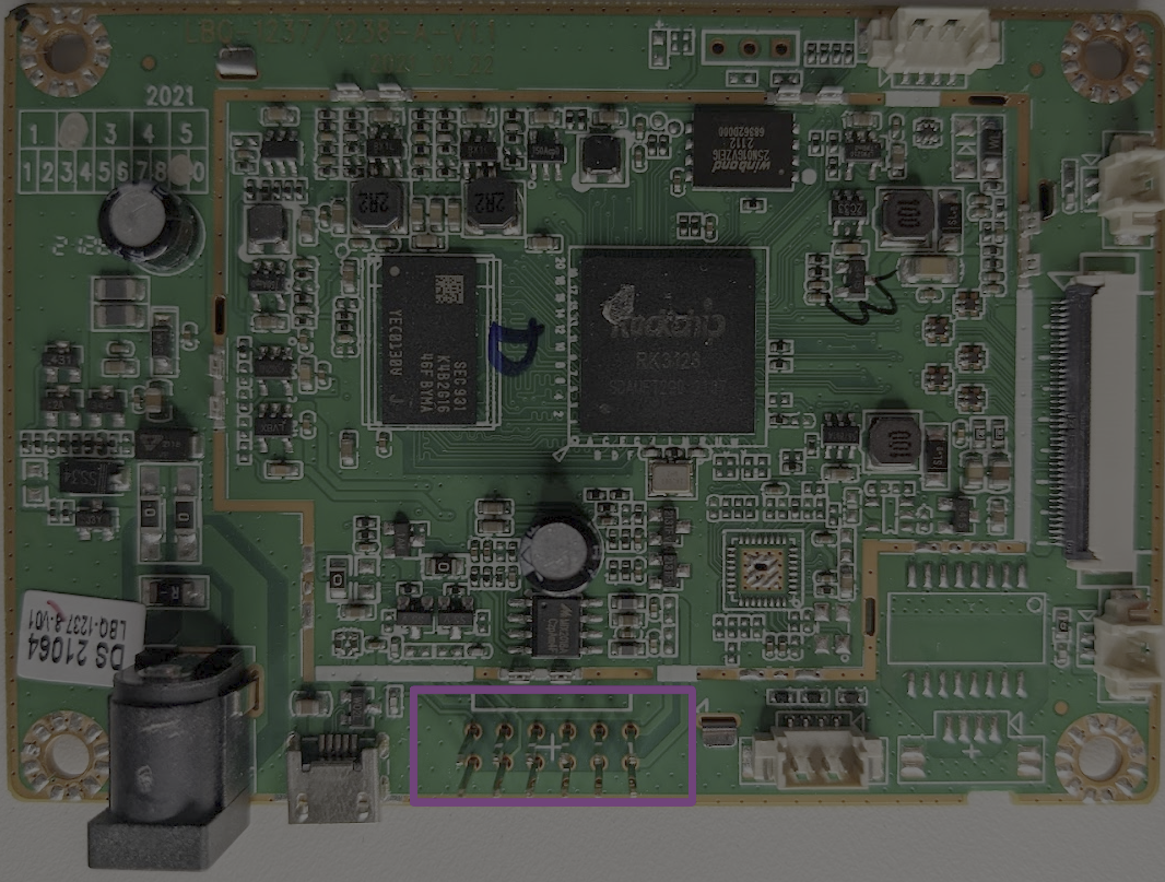
We have identified all of the connections that we had to disconnect to better look at the board. Therefore, there are only a few things left for us to inspect. When examining a PCB, one thing to look for is any unused test pads or vias; I have highlighted the unused headers/pads in the image below.
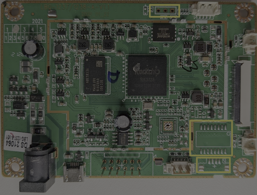
In the above image, we can see that we have three different sets of unpopulated headers or pads. On the top of the PCB, we have three vias; a via is used to make a connection between multiple layers of a PCB. When examining an embedded system, vias such as this are often a good starting point as they may represent a debug header used during development.
The other unpopulated is made up of 16 pads and is indicated by a white rectangle and a small circle. This grouping of pads likely was meant for another integrated circuit that was not needed on this board.
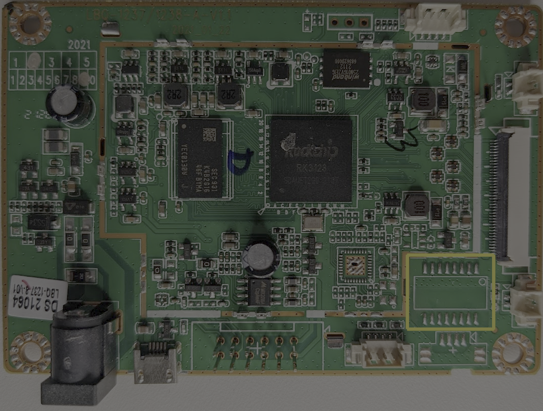
Finally, the last set of pads looks very similar to the connectors used for USB and Audio. When looking at unused pads, four-pin connections like this are often candidates for a debug console via UART; we will examine these headers and discuss UART in the next section.
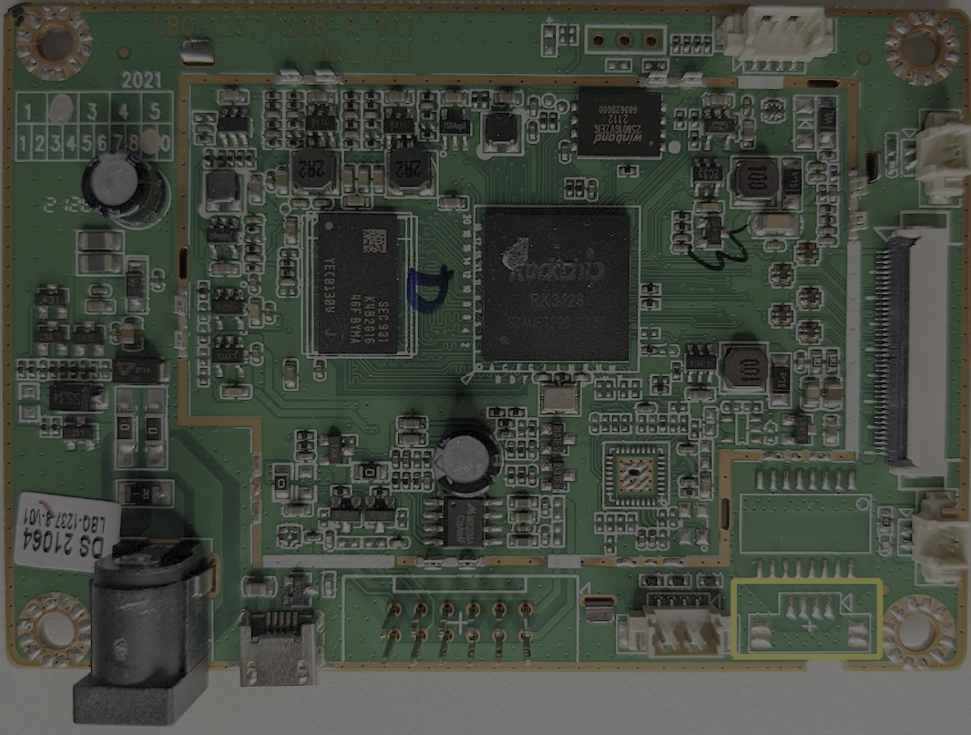
Examining Debug Headers
When looking at unknown headers like those pointed out in the section above, I usually start by measuring the voltage. We can do this using our multimeters. To calculate the voltage on these pads, we will set the multimeter to DC measurement mode and probe the locations of interest while holding our black probe on a ground point. The pins measure as follows:
| Pin | Voltage Level |
|---|---|
| 1 | 0v |
| 2 | 0v |
| 3 | 0v |
| 4 | 0v |
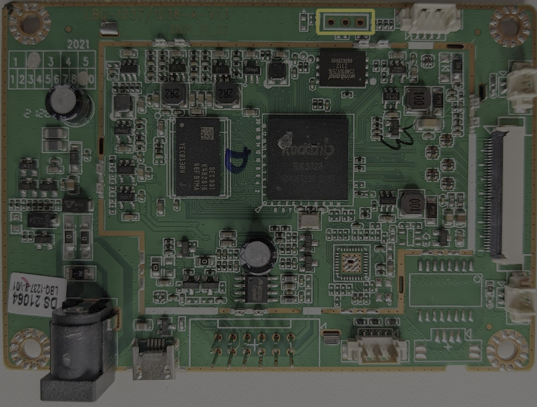
There is no voltage on these lines; while this is disappointing, it is not unexpected. If this were an active UART or another digital signal being transmitted, we would have expected to see some activity in the form of voltage fluctuations. Let's move on to the other three-pin header.
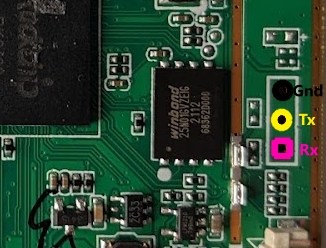
| Pin | Voltage Level | Color |
|---|---|---|
| 1 | 2.7v | Pink |
| 2 | 1.4-3.3v | Yellow |
| 3 | GND | Black |
When measuring this connector, our second pin fluctuates wildly on startup and then settles at 3.3V; see the gif below for an example of what these fluctuations look like:

RE Note: You might not always see voltage fluctuations of this magnitude when searching for a serial port. The fluctuations are directly correlated to how active the signal is, meaning that if there is little traffic, you will see little to no fluctuation. If you suspect that you have a UART header or some kind of digital interface, it's always a good idea to check with a logic analyzer.
We see what might look like signal activity (based on the voltage fluctuations). Next, we will examine this traffic with our logic analyzer. Logic analyzers help us convert these voltage fluctuations into a human-readable sequence of ones and zeros. To do this, we will connect our logic analyzer to our two points of interest using female-female jumper wires as shown below:
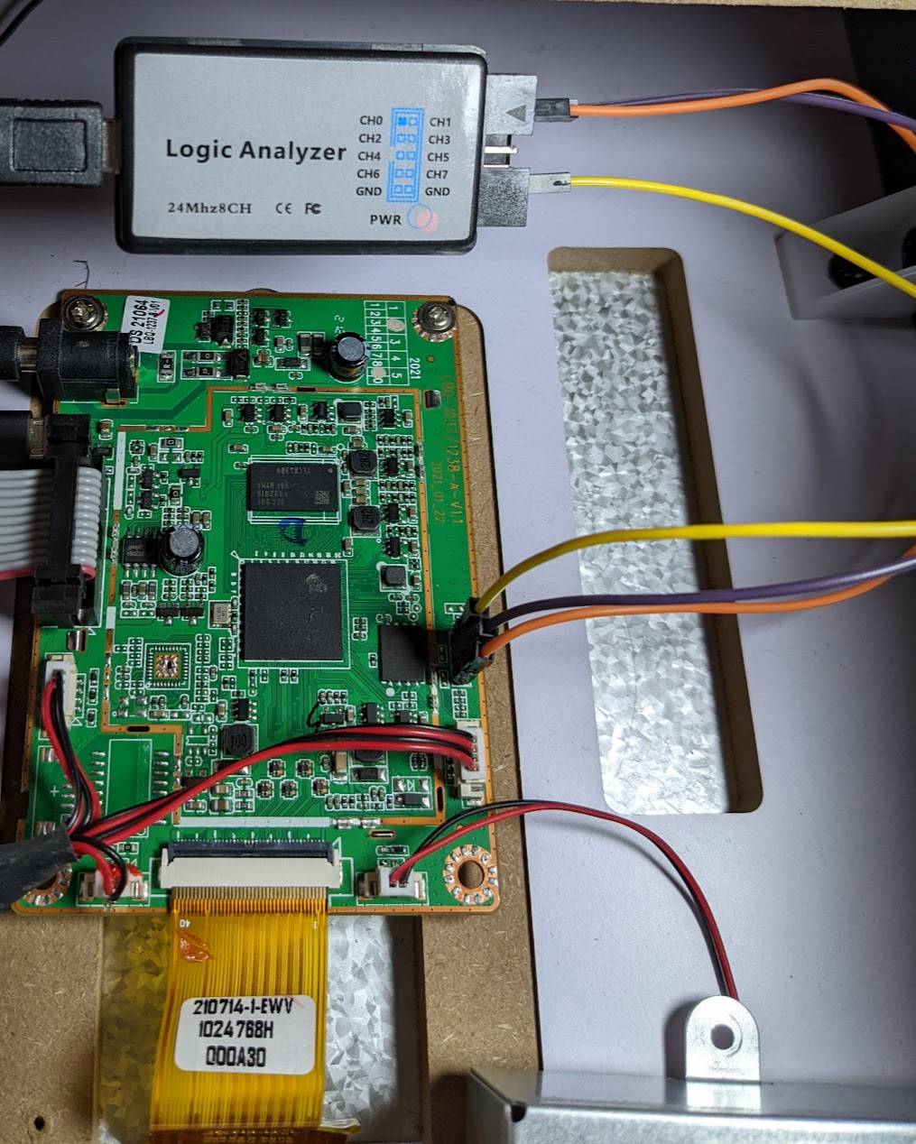
With the analyzer connected, we will launch Pulseview and select our analyzer from the drop-down menu; this device is displayed as a "Saleae Logic" device in pulseview. The max capture rate for this analyzer is 24MHz which we will be using for our analysis. We also need to specify the sample count, which I have set to 500G Samples.
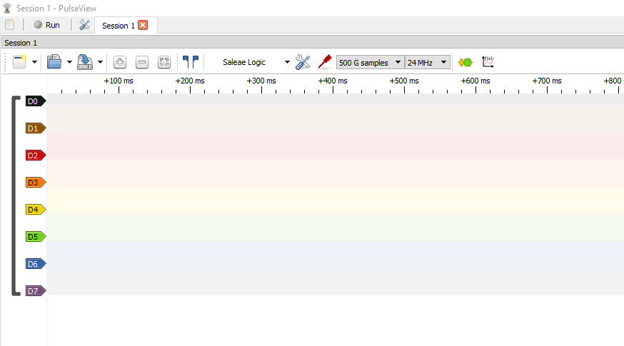
We will launch a capture by clicking Run, then power up the cabinet with these settings.
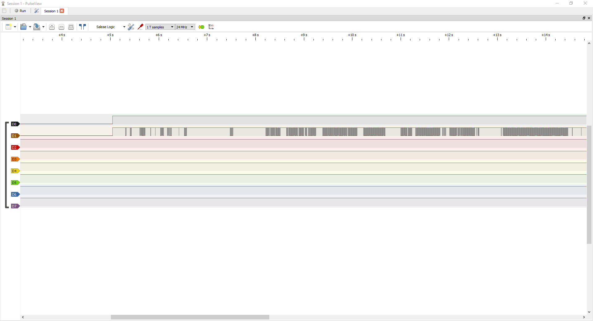
Success! We have captured some traffic; before we go further in pulseview, let's talk more about how UART works at a signal level. We have confirmed that there is some kind of traffic being transmitted over these lines; next, we need to learn a little more about UART traffic and how to analyze it.
UART
UART stands for Universal Asynchronous Receiver Transmitter. UART is a two-wire asynchronous serial protocol that allows two devices to communicate. The two lines required for each party are the Transmit (Tx) and receive (Rx) lines. A UART can be used for many things on an embedded system, including communicating with other processors, sensor communications, and debug access. UART is an asynchronous protocol meaning that there is no clock signal required. Instead, both communicating parties are preconfigured to communicate at a certain speed, referred to as the baud rate. The baud rate is measured in bits per second.
A UART packet/transmission consists of the following fields:
| Bit Position | Name | Description |
|---|---|---|
| 0:1 | Start bit | Used to signify the start of a packet |
| 1:9 | Data bits (this can also be configured to be any value really, but is commonly 8) | The data to be sent/read, note that data is typically sent with the least significant bit first |
| 9:10 | Parity bit | one if the data bits contain an off number of ones, 0 otherwise |
| 10:12 | Stop bits | This signifies that the packet has ended |
Even with the packet definitions above, it is difficult for us to determine the contents of our logic capture. Luckily for us, Pulseview has a UART decoder that we can take advantage of.
Decoding UART Traffic
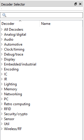
Using pulseview, we can attempt to decode this traffic and see if it indeed is an active UART. To set up a decoder, click the green and yellow symbols below. This will open the decoder selection window, type uart in the search bar, and select the UART decoder.

Next, we need to configure the UART decoder. We need to select the appropriate channels and set any protocol-specific parameters this decoder needs. See the configurable parameters below:
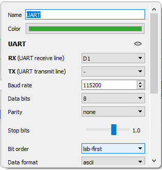
First, we select our Rx line as our channel containing traffic; in our case, that will be D1. For all of the other fields, we will leave them at their default values, 8-bit data width, no parity, etc.
There is one thing that we need to investigate and fill in ourselves: the baud rate. Remember that the two parties must agree on the baud rate ahead of time; there is no negotiation/startup sequence. We will need to determine this baud rate ourselves; otherwise, the decoder will not know how to parse these signals correctly. To determine the baud rate, we can do the following.
- Zoom in on what appears to be one of the smallest pulses (presumably, this represents one bit being sent over the wire)
- Select the pulse width using the data markers in Pulseview, click the button shown below to enable them:

- With the small pulse range selected, Pulseview will automatically calculate the frequency and give us a measurement in hertz, as shown in the screenshot below.
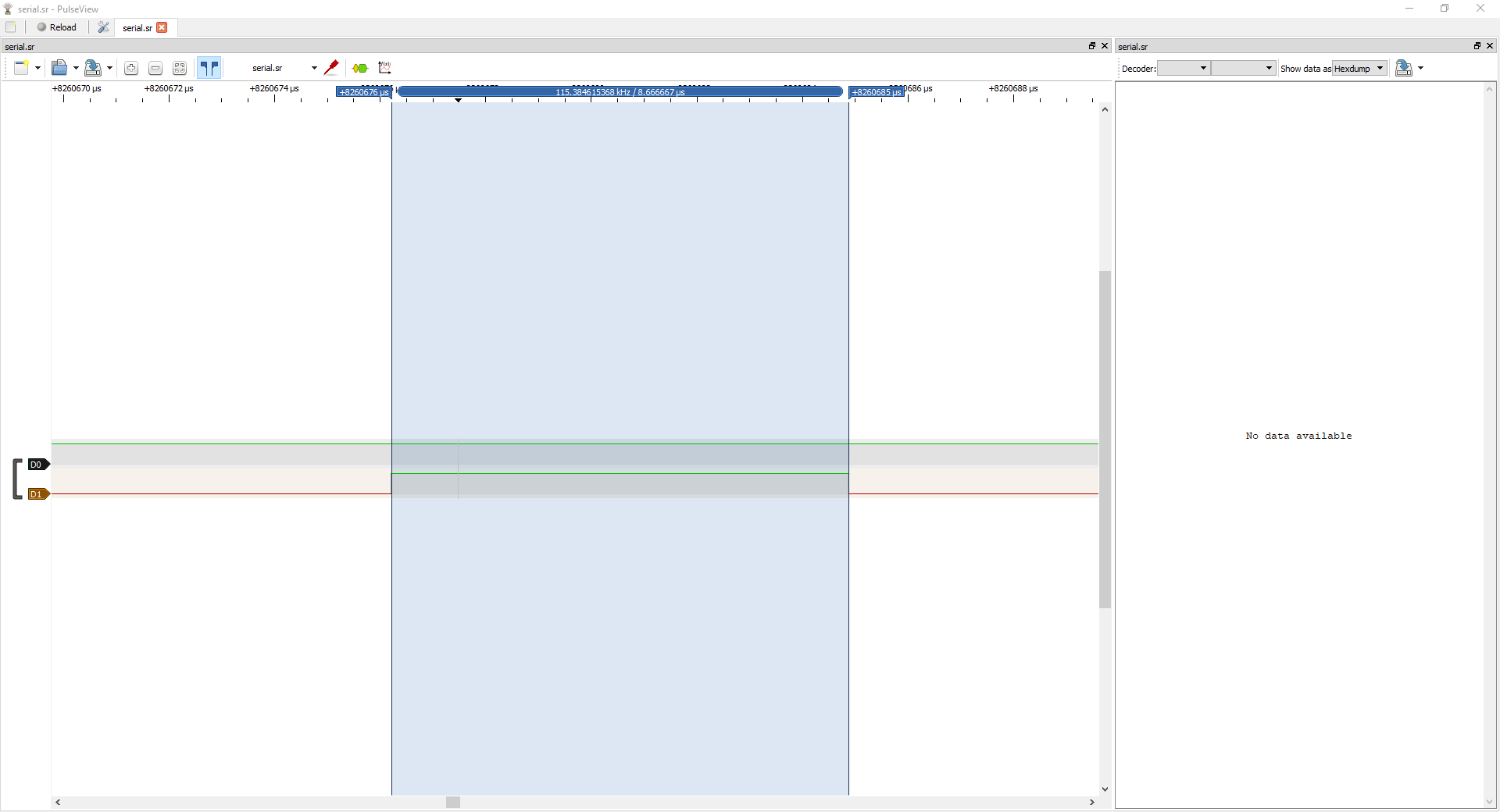
Hertz is measured in cycles per second; recall that our baud rate is a measurement of bits per second. So, therefore, if we have highlighted one bit being sent over the wire and the frequency of that pulse, we also have the baud rate.
Our calculated frequency according to Pulseview is 115.384 kHz, which translates to a baud rate of 115385 bits/s. Those familiar with debug consoles might notice that this is very close to a commonly used baud rate of 115200. So let's plug that value into our decoder and see what happens.
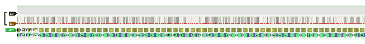
If we look at the screenshot below, we can see that we have what appears to be a valid debug log.
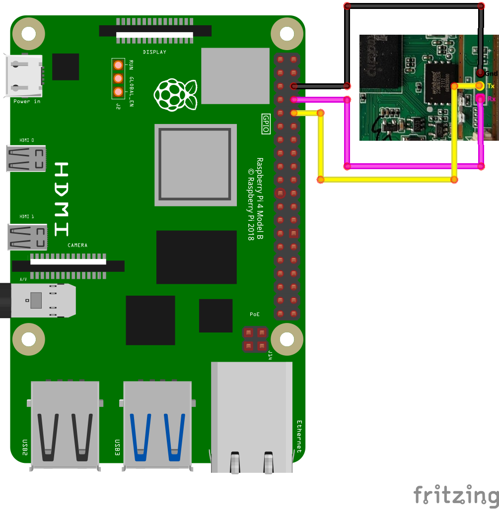
We have an active UART and know its baud rate, but now we need to find a way to interface with it. To do this, we will use the Raspberry Pi. The updated cabinet the pinout is as follows:
Configuring the Raspberry Pi
The Raspberry Pi has multiple UARTS available; the UART that we will use has been highlighted in the image below:

We will need to ensure that the appropriate device tree blob is enabled to enable this UART. The purpose of a device tree blob is to provide a way for the kernel to understand the available hardware peripherals. The kernel will read this binary information at startup and enumerate the specified peripherals. When reverse engineering an embedded Linux system, extracting this information can be beneficial because it can be decompiled and outline where various peripherals are in memory.
All relevant device tree blobs on the raspberry pi can be located in /boot/overlays/. In this folder, you will find device tree binary objects for multiple hardware configurations, some for specific hats (custom PCBs designed for the Pi) that can be attached to the Pi and others for enabling the assorted IO peripherals. We can enable the appropriate DTB for the UART peripheral using the raspi-config tool.
Using Raspi Config
raspi-config is a user-space tool that allows us to configure various aspects of the Raspberry Pi, one of which is enabling the various external interfaces. We're going to use raspi-config to enable the UART interface; start by launching the tool as follows:
sudo raspi-config
This will cause the following screen to appear:
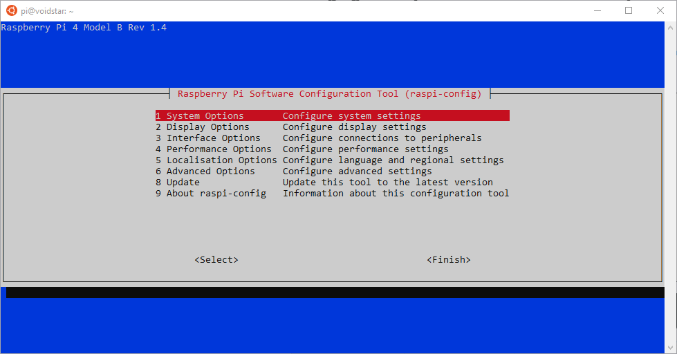
Next, we will select Interface Options, and then Serial Port as shown in the image below:
After selecting this option, we will be presented with two questions:
- Would you like a login shell to be accessible over serial?
- No
- Would you like the serial port hardware to be enabled?
- Yes
We have now enabled the UART on the Raspberry Pi. Next, we need to connect it to our cabinet. We will connect Tx of the cabinet to Rx of the Pi, and Rx of the cabinet to Tx of the Pi:
UART Tools
Using the UART interface on the Raspberry Pi, we can attempt to connect to this serial port on the target. In order to interact with this serial port, we will use the screen utility. Screen requires that we pass it a device and baud rate when interfacing with a UART; since we know the baud rate from our previous segment, we will run screen as follows:
sudo screen -L -Logfile cabinet-bootup.log /dev/ttyS0 115200
-L -Logfile cabinet-bootup.log- Record the session to the ``cabinet-bootup.log``` file/dev/ttyS0- Serial device to use115200- Baud rate
We can now power on the cabinet after configuring our UART and launching screen. When we power on the cabinet, we see the following:
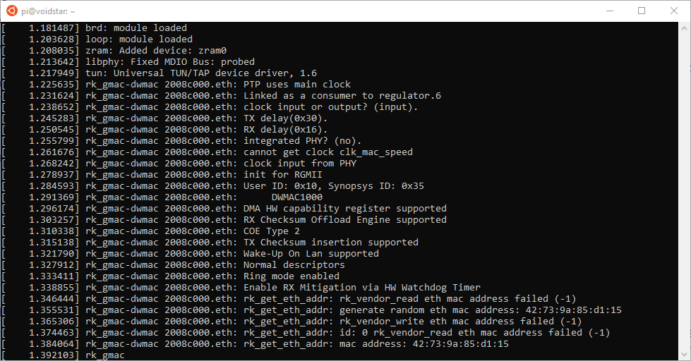
And eventually, we find ourselves at a console:
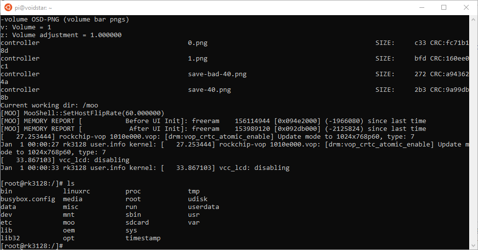
We have a root console now; we can explore the filesystem, see what is running on the target and learn more about how it was constructed. Our next step will be to image the partitions if possible; let's start by looking at what partitions are mounted:
[root@rk3128:/]# mount
/dev/root on / type squashfs (ro,relatime)
devtmpfs on /dev type devtmpfs (rw,relatime,size=103544k,nr_inodes=25886,mode=755)
proc on /proc type proc (rw,relatime)
devpts on /dev/pts type devpts (rw,relatime,gid=5,mode=620,ptmxmode=000)
tmpfs on /dev/shm type tmpfs (rw,relatime,size=112248k,nr_inodes=28062,mode=777)
tmpfs on /tmp type tmpfs (rw,relatime,size=112248k,nr_inodes=28062)
tmpfs on /tmp type tmpfs (rw,nosuid,nodev,relatime,size=112248k,nr_inodes=28062,mode=755)
sysfs on /sys type sysfs (rw,relatime)
debug on /sys/kernel/debug type debugfs (rw,relatime)
pstore on /sys/fs/pstore type pstore (rw,relatime)
/dev/root on /var type squashfs (ro,relatime)
tmpfs on /tmp type tmpfs (rw,nosuid,nodev,relatime,size=112248k,nr_inodes=28062,mode=755)
/dev/rkflash0p5 on /userdata type ext2 (rw,relatime)
none on /sys/kernel/config type configfs (rw,relatime)
adb on /dev/usb-ffs/adb type functionfs (rw,relatime)
Our root filesystem is mounted as read-only and is using the squashfs format. In addition, another partition is mounted that is labeled userdata. If we examine the available block devices, we see the following:
[root@rk3128:/]# ls -lathr /dev/block/by-name/
lrwxrwxrwx    1 root     root          16 Jan  1 00:00 userdata -> ../../rkflash0p5
lrwxrwxrwx    1 root     root          16 Jan  1 00:00 uboot -> ../../rkflash0p1
lrwxrwxrwx    1 root     root          16 Jan  1 00:00 trust -> ../../rkflash0p2
lrwxrwxrwx    1 root     root          16 Jan  1 00:00 rootfs -> ../../rkflash0p4
lrwxrwxrwx    1 root     root          16 Jan  1 00:00 boot -> ../../rkflash0p3
drwxr-xr-x    3 root     root         380 Jan  1 00:00 ..
drwxr-xr-x    2 root     root         140 Jan  1 00:00 .
We can see that we presumably have our SPI flash device at /dev/rkflash0. To get an image of this block device, we can plug a USB stick into the cabinet's USB port and use the dd utility. When we insert a USB flash drive, it is enumerated at /dev/sda we can image the USB drive with the contents of the SPI flash using the following command:
sudo dd if=/dev/rkflash0 of=/dev/sda status=progress
If we plug the USB drive into the Pi and examine the partition table we see that the appropriate partitions have been imaged to the drive!
pi@voidstar:~ $ lsblk
NAME        MAJ:MIN RM  SIZE RO TYPE MOUNTPOINT
sda           8:0    1 57.8G  0 disk
├─sda1        8:1    1    4M  0 part
├─sda2        8:2    1    2M  0 part
├─sda3        8:3    1    9M  0 part
├─sda4        8:4    1 80.8M  0 part
└─sda5        8:5    1    8M  0 part
Now we have a backup of the flash, which is the first step that we should take when attempting to modify an embedded system; before we try to modify anything or reflash any partitions, we should make sure that we have a way to recover them; to do this, we will investigate the bootloader. As a starting point, lets take note of the following line at the beginning of the bootup log:
CLK: (uboot. arm: enter 600000 KHz, init 600000 KHz, kernel 0N/A)
  apll 600000 KHz
  dpll 600000 KHz
  cpll 650000 KHz
  gpll 594000 KHz
  armclk 600000 KHz
  aclk_cpu 148500 KHz
  hclk_cpu 74250 KHz
  pclk_cpu 74250 KHz
  aclk_peri 148500 KHz
  hclk_peri 74250 KHz
  pclk_peri 74250 KHz
Net:   Net Initialization Skipped
No ethernet found.
Hit key to stop autoboot('CTRL+C'):  0
If we hold down Ctrl-c in our screen prompt while powering the cabinet, we see the following:
Hit key to stop autoboot('CTRL+C'):  0
=> <INTERRUPT>
We now have a UBoot prompt; before we dive into this further, let's talk about UBoot and how it works.
UBoot
UBoot is an open-source bootloader commonly used in embedded systems. It has support for a wide variety of architectures and CPU types. However, the responsibility of UBoot is usually to load the operating system kernel or the main application for the embedded system.
UBoot also includes debug utilities useful during your reverse engineering efforts; most notable is the UBoot command prompt.
UBoot Commands
The UBoot console can contain a large number of built-in utilities. These utilities can be used during the standard boot process (often through environment variables) or at the UBoot command line. The available commands will vary depending on how the UBoot image was built.
Now that we have discovered a UBoot console let's start by seeing which commands are publically available to us by running the help command
  android_print_hdr base bdinfo bidram_dump BMP boot boot_android bootavb
  bootd bootm bootp bootrkp bootz charge cmp coninfo cp crc32 ...
=>
?       - alias for 'help'
android_print_hdr- print android image header
base    - print or set address offset
bdinfo  - print Board Infostructure
bidram_dump- Dump bidram layout
BMP     - manipulate BMP image data
boot    - boot default, i.e., run 'bootcmd'
boot_android- Execute the Android Bootloader flow.
bootavb - Execute the Android avb a/b boot flow.
bootd   - boot default, i.e., run 'bootcmd'
bootm   - boot application image from memory
bootp   - boot image via network using BOOTP/TFTP protocol
bootrkp - Boot Linux Image from rockchip image type
Bootz   - boot Linux zImage image from memory
charge  - Charge display
CMP     - memory compare
coninfo - print console devices and information
cp      - memory copy
crc32   - checksum calculation
DHCP    - boot image via network using DHCP/TFTP protocol
dm      - Driver model low level access
download- enter rockusb/bootrom download mode
dtimg   - manipulate dtb/dtbo Android image
dump_atags- Dump the content of the atags
dump_irqs- Dump IRQs
echo    - echo args to console
editenv - edit environment variable
env     - environment handling commands
exit    - exit script
ext2load- load binary file from a Ext2 filesystem
ext2ls  - list files in a directory (default /)
ext4load- load binary file from a Ext4 filesystem
ext4ls  - list files in a directory (default /)
ext4size- determine a file's size
false   - do nothing, unsuccessfully
fastboot- use USB or UDP Fastboot protocol
fatinfo - print information about filesystem
fatload - load binary file from a dos filesystem
fatls   - list files in a directory (default /)
fantasize - determine a file's size
fatwrite- write file into a dos filesystem
fdt     - flattened device tree utility commands
fstype  - Lookup a filesystem type
go      - start application at address 'addr'
gpt     - GUID Partition Table
help    - print command description/usage
iomem   - Show iomem data by device compatible(high priority) or node name
lcdputs - print string on video framebuffer
load    - load binary file from a filesystem
loop    - infinite loop on address range
ls      - list files in a directory (default /)
MD      - memory display
mii     - MII utility commands
mm      - memory modify (auto-incrementing address)
mmc     - MMC subsystem
mmcinfo - display MMC info
MW      - memory write (fill)
NFS     - boot image via network using NFS protocol
nm      - memory modify (constant address)
part    - disk partition related commands
ping    - Send ICMP ECHO_REQUEST to network host
printenv- print environment variables
pxe     - commands to get and boot from pxe files
rbrom   - Perform RESET of the CPU
reboot  - Perform RESET of the CPU, alias of 'reset'
reset   - Perform RESET of the CPU
rkimgtest- Test if storage media have rockchip image
rknand  - rockchip nand flash sub-system
rksfc   - rockchip SFC sub-system
rktest  - Rockchip board modules test
rockchip_show_bmp- load and display BMP from resource partition
rockchip_show_logo- load and display log from resource partition
rocks - Use the rockusb Protocol
run     - run commands in an environment variable
save    - save file to a filesystem
setcurs - set cursor position within screen
setenv  - set environment variables
showvar - print local hushshell variables
size    - determine a file's size
source  - run script from memory
sysboot - command to get and boot from syslinux files
sysmem_dump- Dump system layout
sysmem_search- Search a available system region
test    - minimal test like /bin/sh
TFTP    - download image via network using TFTP protocol
true    - do nothing, successfully
ums     - Use the UMS [USB Mass Storage]
USB     - USB sub-system
usbboot - boot from USB device
version - print monitor, compiler, and linker version
=>
Before we spend too much time reviewing every command, let's revisit our main objective, which is to be able to read and write the root filesystem partition from the bootloader in case we need to recover this cabinet later. The following commands immediately stand out as they involve memory reading and writing:
download- enter rockusb/bootrom download mode
dtimg   - manipulate dtb/dtbo Android image
dump_atags- Dump the content of the atags
ext2load- load binary file from a Ext2 filesystem
ext2ls  - list files in a directory (default /)
ext4load- load binary file from a Ext4 filesystem
ext4ls  - list files in a directory (default /)
ext4size- determine a file's size
fastboot- use USB or UDP Fastboot protocol
fatinfo - print information about filesystem
fatload - load binary file from a dos filesystem
fatls   - list files in a directory (default /)
fantasize - determine a file's size
fatwrite- write file into a dos filesystem
mm      - memory modify (auto-incrementing address)
rknand  - rockchip nand flash sub-system
rksfc   - rockchip SFC sub-system
ums     - Use the UMS [USB Mass Storage]
USB     - USB sub-system
Next, we can review the environment variables that this bootloader has configured using the printenv command. This will give us more context surrounding how this platform boots, what memory addresses are in use and what other interfaces may be available.
UBoot Environment Variables
Various environment variables can be configured when building or configuring a UBoot image for a device. These environment variables control what operations are performed on startup. There are multiple ways that these variables can be stored. Sometimes they are hardcoded into the binary itself; they can also reside on a flash partition, allowing users to modify them from the UBoot prompt.
We can examine the environment variables with the printenv command:
=> printenv
arch=arm
baudrate=115200
board=evb_rk3128
board_name=evb_rk3128
boot_a_script=load ${devtype} ${devnum}:${distro_bootpart} ${scriptaddr} ${prefix}${script}; source ${scriptaddr}
boot_extlinux=sysboot ${devtype} ${devnum}:${distro_bootpart} any ${scriptaddr} ${prefix}extlinux/extlinux.conf
boot_net_usb_start=usb start
boot_prefixes=/ /boot/
boot_script_dhcp=boot.scr.uimg
boot_scripts=boot.scr.uimg boot.scr
boot_targets=mmc1 mmc0 rknand0 usb0 pxe dhcp
bootargs=storagemedia=nand androidboot.storagemedia=nand androidboot.mode=normal
bootcmd=boot_android ${devtype} ${devnum};bootrkp;run distro_bootcmd;
bootcmd_dhcp=run boot_net_usb_start; if dhcp ${scriptaddr} ${boot_script_dhcp}; then source ${scriptaddr}; fi;
bootcmd_mmc0=setenv devnum 0; run mmc_boot
bootcmd_mmc1=setenv devnum 1; run mmc_boot
bootcmd_pxe=run boot_net_usb_start; dhcp; if pxe get; then pxe boot; fi
bootcmd_rknand0=setenv devnum 0; run rknand_boot
bootcmd_usb0=setenv devnum 0; run usb_boot
bootdelay=0
cpu=armv7
devnum=0
devtype=spinand
distro_bootcmd=for target in ${boot_targets}; do run bootcmd_${target}; done
ethaddr=d2:79:07:fc:f7:89
fdt_addr1_r=0x61700000
fdt_addr_r=0x68300000
kernel_addr1_r=0x62008000
kernel_addr_r=0x62008000
mmc_boot=if mmc dev ${devnum}; then setenv devtype mmc; run scan_dev_for_boot_part; fi
pxefile_addr1_r=0x60600000
pxefile_addr_r=0x60600000
ramdisk_addr1_r=0x63000000
ramdisk_addr_r=0x6a200000
rkimg_bootdev=if mmc dev 1 && rkimgtest mmc 1; then setenv devtype mmc; setenv devnum 1; echo Boot from SDcard;elif mmc dev 0; then setenv devtype mmc; setenv devnum 0;elif mtd_blk dev 0; then setenv devtype mtd; setenv devnum 0;elif mtd_blk dev 1; then setenv devtype mtd; setenv devnum 1;elif mtd_blk dev 2; then setenv devtype mtd; setenv devnum 2;elif rknand dev 0; then setenv devtype rknand; setenv devnum 0;elif rksfc dev 0; then setenv devtype spinand; setenv devnum 0;elif rksfc dev 1; then setenv devtype spinor; setenv devnum 1;fi;
scan_dev_for_boot=echo Scanning ${devtype} ${devnum}:${distro_bootpart}...; for prefix in ${boot_prefixes}; do run scan_dev_for_extlinux; run scan_dev_for_scripts; done;
scan_dev_for_boot_part=part list ${devtype} ${devnum} -bootable devplist; env exists devplist || setenv devplist 1; for distro_bootpart in ${devplist}; do if fstype ${devtype} ${devnum}:${distro_bootpart} bootfstype; then run scan_dev_for_boot; fi; done
scan_dev_for_extlinux=if test -e ${devtype} ${devnum}:${distro_bootpart} ${prefix}extlinux/extlinux.conf; then echo Found ${prefix}extlinux/extlinux.conf; run boot_extlinux; echo SCRIPT FAILED: continuing...; fi
scan_dev_for_scripts=for script in ${boot_scripts}; do if test -e ${devtype} ${devnum}:${distro_bootpart} ${prefix}${script}; then echo Found U-Boot script ${prefix}${script}; run boot_a_script; echo SCRIPT FAILED: continuing...; fi; done
scriptaddr=0x60500000
scriptaddr1=0x60500000
serial#=c3d9b8674f4b94f6
soc=rockchip
stderr=serial,vidconsole
stdout=serial,vidconsole
usb_boot=usb start; if usb dev ${devnum}; then setenv devtype usb; run scan_dev_for_boot_part; fi
vendor=rockchip

Environment size: 3477/32764 bytes
=>
There are a few variables of interest that I'd like to point out in the table below:
| Variable | Significance |
|---|---|
bootcmd |
This command is used to define the default boot behavior |
board=evb_rk3128 |
This identifies the CPU / development board in use |
devtype=spinand |
This defines the flash device type in use |
At this point, if we cross-reference the information that we gathered during our hardware review, we see consistent results. We assumed after our hardware review that the SPI flash was the main method of storage, and this assumption is being validated in the UBoot environment variables and the available commands.
Let's start by examining the rksfc commands; a quick google search tells us that this is RockChip's SPI SFC (serial flash controller) interface tool. This command has the following subcommands available:
=> rksfc
rksfc - rockchip sfc sub-system

Usage:
rksfc scan - scan Sfc devices
rksfc info - show all available Sfc devices
rksfc device [dev] - show or set current Sfc device
    dev 0 - spinand
    dev 1 - spinor
rksfc part [dev] - print partition table of one or all Sfc devices
rksfc read addr blk# cnt - read `cnt' blocks starting at block
    `blk#' to memory address `addr'
rksfc write addr blk# cnt - write `cnt' blocks starting at block
    `blk#' from memory address `addr'
We can get the information about the SPI flash with the following commands:
=> rksfc scan
=> rksfc info
Device 0: Vendor: 0x0308 Rev: V1.00 Prod: rkflash-SpiNand
            Type: Hard Disk
            Capacity: 107.7 MB = 0.1 GB (220672 x 512)
=> rksfc device 0

Device 0: Vendor: 0x0308 Rev: V1.00 Prod: rkflash-SpiNand
            Type: Hard Disk
            Capacity: 107.7 MB = 0.1 GB (220672 x 512)
... is now current device
=> rksfc part 0

Partition Map for SPINAND device 0  --   Partition Type: EFI

Part  Start LBA End LBA   Name
  Attributes
  Type GUID
  Partition GUID
  1 0x00002000  0x00003fff  "uboot"
  attrs:  0x0000000000000000
  type: ea450000-0000-424f-8000-0cd500004c0a
  guid: 325b0000-0000-4d21-8000-6e10000051c5
  2 0x00004000  0x00004fff  "trust"
  attrs:  0x0000000000000000
  type: b44a0000-0000-4121-8000-4e1600002902
  guid: 62500000-0000-4f7f-8000-4a7800006ca1
  3 0x00005000  0x000097ff  "boot"
  attrs:  0x0000000000000000
  type: 6c1e0000-0000-4833-8000-5d07000065c4
  guid: 442c0000-0000-4c4c-8000-2ed400005ecb
  4 0x00009800  0x00031dff  "rootfs"
  attrs:  0x0000000000000000
  type: 9b050000-0000-4e44-8000-5f3000007157
  guid: 614e0000-0000-4b53-8000-1d28000054a9
  5 0x00031e00  0x00035dde  "userdata"
  attrs:  0x0000000000000000
  type: c8050000-0000-4b18-8000-3b1a000041c3
  guid: 40780000-0000-493e-8000-688900001525
=>
Using these commands, we can learn more about the SPI flash. We can see that the block size is 512 and that the chip contains a total of 220672 (0x35E00) blocks separated into five partitions:
- uboot - Likely contains our UBoot image / first stage bootloader
- trust - Trusted execution environment image
- boot - Kernel image / ramdisk
- rootfs - Our largest partition, the root filesystem of the kernel
- user data - User-specific data, likely used for high scores, user settings, etc
Note that this data matches what we saw earlier from the root console prompt. We now understand how the flash is partitioned and what data might be available, but how can we read/write this data without soldering additional lines to the board? If we examine the usb command, we see the following:
=> usb
usb - USB sub-system

Usage:
usb start - start (scan) USB controller
usb reset - reset (rescan) USB controller
usb stop [f] - stop USB [f]=force stop
usb tree - show USB device tree
usb info [dev] - show available USB devices
usb test [dev] [port] [mode] - set USB 2.0 test mode
    (specify port 0 to indicate the device's upstream port)
    Available modes: J, K, S[E0_NAK], P[acket], F[orce_Enable]
usb storage - show details of USB storage devices
usb dev [dev] - show or set current USB storage device
usb part [dev] - print partition table of one or all USB storage    devices
usb read addr blk# cnt - read `cnt' blocks starting at block `blk#'
    to memory address `addr'
usb write addr blk# cnt - write `cnt' blocks starting at block `blk#'
    from memory address `addr'
Using the USB port on the side of the cabinet, if we insert a device and run USB start followed by USB info the following output is generated:
=> usb start
starting USB...
Bus usb@10180000: Bus usb@101c0000: USB EHCI 1.00
Bus usb@101e0000: USB OHCI 1.0
scanning bus usb@10180000 for devices... 1 USB Device(s) found
scanning bus usb@101c0000 for devices... RKPARM: Invalid parameter part table
2 USB Device(s) found
scanning bus usb@101e0000 for devices... 1 USB Device(s) found
       scanning usb for storage devices... 1 Storage Device(s) found
=> usb info
1: Hub,  USB Revision 1.10
 -  U-Boot Root Hub
 - Class: Hub
 - PacketSize: 8  Configurations: 1
 - Vendor: 0x0000  Product 0x0000 Version 0.0
   Configuration: 1
   - Interfaces: 1 Self Powered 0mA
     Interface: 0
     - Alternate Setting 0, Endpoints: 1
     - Class Hub
     - Endpoint 1 In Interrupt MaxPacket 2 Interval 255ms

1: Hub,  USB Revision 2.0
 - u-boot EHCI Host Controller
 - Class: Hub
 - PacketSize: 64  Configurations: 1
 - Vendor: 0x0000  Product 0x0000 Version 1.0
   Configuration: 1
   - Interfaces: 1 Self Powered 0mA
     Interface: 0
     - Alternate Setting 0, Endpoints: 1
     - Class Hub
     - Endpoint 1 In Interrupt MaxPacket 8 Interval 255ms

2: Mass Storage,  USB Revision 2.10
 -          USB DISK 3.0 0719146D1CBF9257
 - Class: (from Interface) Mass Storage
 - PacketSize: 64  Configurations: 1
 - Vendor: 0x13fe  Product 0x6300 Version 1.0
   Configuration: 1
   - Interfaces: 1 Bus Powered 498mA
     Interface: 0
     - Alternate Setting 0, Endpoints: 2
     - Class Mass Storage, Transp. SCSI, Bulk only
     - Endpoint 1 In Bulk MaxPacket 512
     - Endpoint 2 Out Bulk MaxPacket 512

1: Hub,  USB Revision 1.10
 -  U-Boot Root Hub
 - Class: Hub
 - PacketSize: 8  Configurations: 1
 - Vendor: 0x0000  Product 0x0000 Version 0.0
   Configuration: 1
   - Interfaces: 1 Self Powered 0mA
     Interface: 0
     - Alternate Setting 0, Endpoints: 1
     - Class Hub
     - Endpoint 1 In Interrupt MaxPacket 2 Interval 255ms
Excellent, we can see that the USB stack enumerates successfully and detects our mass storage device.
Before we continue, let's review what we know about our UBoot environment:
- Examining the environment variables gave us usable addresses in RAM
- Using the
rksfc readutility, we can read SPI flash sectors into RAM - Using the USB commands, we can enumerate a USB device and write to it
We could read the SPI flash into RAM, attach a USB device, and then write the SPI flash data to the USB device using the USB write command. If this method works, we should also be able to recover the flash images by inverting the steps, reading data from the USB drive, and writing it back to flash using rksfc write. Let's start by testing a read.
First, we will try to read the entire SPI flash into RAM with the following command for our destination address we will try the address stored in $ramdisk_addr_r which is 0x6a200000:
=> rksfc read $ramdisk_addr_r 0 0x35E00

spinand read: device 0 block # 0, count 220672 ... undefined instruction
pc : ce695528  lr : 1fadca4d
sp : 6be17bd8  ip : 00000020     fp : 60093204
r10: 00004254  r9 : 6be1bdf8     r8 : ad758c77
r7 : ebaa79cb  r6 : b052b720     r5 : 36395b84  r4 : f3a911be
r3 : 780fb750  r2 : 00000000     r1 : 600a62fc  r0 : 200a226c
Flags: nZcv  IRQs on  FIQs off  Mode SVC_32


Call trace:
  PC:   [< ce695528 >]
  LR:   [< 1fadca4d >]

Stack:
        [< ce695528 >]

Copy info from "Call trace..." to a file(eg. dump.txt), and run
command in your U-Boot project: ./scripts/stacktrace.sh dump.txt

Resetting CPU ...

### ERROR ### Please RESET the board ###
This didn't work; we somehow triggered an undefined instruction exception. We likely clobbered something in that UBoot was utilizing; let's see what happens when we try another address that is lower in memory:
=> rksfc read $scriptaddr 0 0x35E00

spinand read: device 0 block # 0, count 220672 ... 220672 blocks read: OK
Moving to a lower address in RAM allowed the read to complete without clobbering anything; let's see if we can now write this data back to the USB drive:
usb write addr blk# cnt - write `cnt' blocks starting at block `blk#'
    from memory address `addr'
=> usb write $scriptaddr 0 0x35E00

usb write: device 0 block # 0, count 220672 ... 220672 blocks written: OK
=>
Now let's take a look at the contents of this drive by inserting it into the Raspberry Pi and see what we have:
pi@voidstar:~ $ lsblk
NAME        MAJ:MIN RM  SIZE RO TYPE MOUNTPOINT
sda           8:0    1 57.8G  0 disk
├─sda1        8:1    1    4M  0 part
├─sda2        8:2    1    2M  0 part
├─sda3        8:3    1    9M  0 part
├─sda4        8:4    1 80.8M  0 part
└─sda5        8:5    1    8M  0 part
Here we can see that the partition table on our USB drive matches what was displayed in the output of the rksfc part 0 command. Next, we will use the dd utility to extract the various partitions for analysis.
pi@voidstar:~/marvel-cab/parts $ sudo dd if=/dev/sda1 of=part1.bin
4194304 bytes (4.2 MB, 4.0 MiB) copied, 0.18225 s, 23.0 MB/s
pi@voidstar:~/marvel-cab/parts $ sudo dd if=/dev/sda2 of=part2.bin
2097152 bytes (2.1 MB, 2.0 MiB) copied, 0.109297 s, 19.2 MB/s
pi@voidstar:~/marvel-cab/parts $ sudo dd if=/dev/sda3 of=part3.bin
9437184 bytes (9.4 MB, 9.0 MiB) copied, 0.386968 s, 24.4 MB/s
pi@voidstar:~/marvel-cab/parts $ sudo dd if=/dev/sda4 of=part4.bin
84672512 bytes (85 MB, 81 MiB) copied, 2.96481 s, 28.6 MB/s
pi@voidstar:~/marvel-cab/parts $ sudo dd if=/dev/sda5 of=part5.bin
8371712 bytes (8.4 MB, 8.0 MiB) copied, 0.314125 s, 26.7 MB/s
pi@voidstar:~/marvel-cab/parts $ file *
part1.bin: data
part2.bin: data
part3.bin: Android bootimg, kernel (0x10008000), second stage (0x10f00000), page size: 2048
part4.bin: Squashfs filesystem, little endian, version 4.0, xz compressed, 71663599 bytes, 1185 inodes, blocksize: 131072 bytes, created: Mon May 31 09:06:53 2021
part5.bin: Linux rev 1.0 ext2 filesystem data (mounted or unclean), UUID=42185cbc-b698-4af6-8a47-e444e5635787, volume name "userdata" (large files)
Thus far, this data matches what we saw when looking at both the mount output on the running system and the partition table from the UBoot menu. Therefore, we can extract the squashfs partition via unsquashfs and attempt to mount the ext2 partition to confirm that they are valid:
pi@voidstar:~/marvel-cab/parts $ unsquashfs part4.bin
Parallel unsquashfs: Using four processors
1029 inodes (1792 blocks) to write
create_inode: could not create character device squashfs-root/dev/console, because you're not superuser!
created 596 files
created 157 directories
created 431 symlinks
created 0 devices
created 0 fifos
pi@voidstar:~/marvel-cab/parts $ ls squashfs-root/
bin  busybox.config  data  dev  etc  lib  lib32  linuxrc  media  misc  mnt  moo  OEM  opt  proc  root  run  sbin  sdcard  sys  timestamp  tmp  udisk  userdata  usr  var
pi@voidstar:~/marvel-cab/parts $ ls squashfs-root/moo/
docs  logo.mp4  MOO  MOO-Ship-MIME_CCADE_MSH_2P-BRK01  SKUShell.MIME_CCADE_SF2_2P.19.exe  start.sh  _ui  assets
It looks like we have a valid root filesystem, and we can now start reverse-engineering the software and learning more about how we might modify this system to play additional games or run custom firmware.
Now that we have confirmed that we can read the flash, let's test and see if we can write this image back to flash using the methods described above:
 => usb read  $scriptaddr 0 0x35E00
 usb read: device 0 block # 0, count 220672 ... 220672 blocks read: OK
 => rksfc write  $scriptaddr 0x35E00 0
 spinand write: device 0 block # 0, count 220672 ... 220672 blocks written: OK
Now we reboot, hoping that our reflashed image still works.
Success! We can now read/write the SPI flash from UBoot using our USB drive; this will be useful for testing patches and firmware modifications!
Now that we can read/write the flash of this cabinet with UBoot, it would be great if we could wipe individual partitions and segments of flash automatically without needing to manually enter ranges each time. To do this, we will use the Depthcharge utility to automate our UBoot interactions!
Scripting UBoot with Depthcharge
When working with UBoot environments, we often need to automate our interactions. for example, in our case, we might want to automate the overwriting of a specific flash partition without having to manually enter the address offsets every time. Luckily for us, the folks over at NCC Group have put together a tool to help us with this called depthcharge. We can use this to automate the process of reading data to and from our flash chip and external USB drive. Our script will need to do the following:
- Connect to the UART and identify the UBoot prompt
- Read and write to the SPI flash using the
rksfc read/writecommands - Read and write to the USB drive using the
USB read/writecommands
First, we need to install the module; we can install depthcharge on the Pi by executing: sudo pip install depthcharge.o
Connect to the UART and identify the UBoot Prompt
We can connect to our UBoot prompt using the following python code:
def console_setup():
    console=Console("/dev/ttyS0",baudrate=115200)
    ctx = Depthcharge(console,arch="arm")
    return ctx
In the above function, we are creating a Console object, which requires that we provide a path to the serial port and the baud rate. This console object is then used to make a Depthcharge context which is what we will use to access the features that Depthcharge has to offer. The depthcharge documentation has a well-documented example of this and describes the setup process in detail.
Flash reads and write via depthcharge
Now that we have connected to our interface, we need to implement the rksfc read and write commands. We can do this using depthcharge's send_command() API. This API call allows us to generate and send a UBoot command to the command prompt and returns the response. In the example below, we construct our read command in the cmd_str variable and ensure that the arguments are formatted properly, then issue the command using the send_command() API.
def rksfc_read(ctx,dest_addr,src_addr,size):
    cmd_str = f"rksfc read  0x{dest_addr:02x} 0x{src_addr:02x} 0x{size:02x}"
    resp = ctx.send_command(cmd_str)
    return resp

def rksfc_write(ctx,dest_addr,src_addr,size):
    cmd_str = f"rksfc write 0x{dest_addr:02x} 0x{src_addr:02x} 0x{size:02x}"
    resp = ctx.send_command(cmd_str)
    time.sleep(10)
    return resp
We now have implemented our flash reads and writes next we need to enumerate the USB stack and then read/write from the flash drive.
USB reads and write via depthcharge
Similar to how we implemented the rksfc commands, we will next implement the usb commands. The process will be similar to that used for the rksfc commands:
'''
usb_setup
This script is used to enumerate and set up the USB port
'''
def usb_setup(ctx,reset=False):
    resps = []
    if not reset:
        resp = ctx.send_command("usb start")
    else:
        resp = ctx.send_command("usb reset")
    resps.append(resp)
    resp = ctx.send_command("usb storage")
    resps.append(resp)
    resp = ctx.send_command("usb dev 0")
    resps.append(resp)
    return resps

'''
USB write addr blk# cnt - write `cnt' blocks starting at block `blk#'
    from memory address `addr'
'''
def usb_raw_write(ctx,source_addr,block,size):
    cmd = f"usb write 0x{source_addr:x} 0x{block:x} 0x{size:x}"
    resp = ctx.send_command(cmd)
    return resp

'''
USB read addr blk# cnt - read `cnt' blocks starting at block `blk#'
    to memory address `addr'
'''
def usb_raw_read(ctx,source_addr,block,size):
    cmd = f"usb read 0x{source_addr:x} 0x{block:x} 0x{size:x}"
    resp = ctx.send_command(cmd)
    return resp
Dumping the flash with Depthcharge
Now that we have the appropriate functions defined, we can try the following:
if __name__ == "__main__":
    log.info("Marvel Super Heroes Depthcharge Test...")
    ctx = console_setup()
    usb_setup(ctx,reset=False)
    # Read the SPI flash into RAM
    rksfc_read(ctx,TARGET_RAM_ADDR,0,0x35E00)
    log.info("Flash read into RAM")
    # Write the data from RAM to a USB drive
    usb_raw_write(ctx,TARGET_RAM_ADDR,0,0x35E00)
    log.info("Flash written to USB")
If we run this script, we see the following output:
pi@voidstar:~/marvel-cab/scripts $ python3 mvc.py
[+] Marvel Super Heroes Deptcharge Test...
[*] Using default payload base address: ${loadaddr} + 32MiB
[*] No user-specified prompt provided. Attempting to determine this.
[*] Identified prompt: =>
[*] Retrieving command list via "help"
[*] Reading environment via "printenv"
[!] Disabling payload deployment and execution due to error(s).
[*] Version: U-Boot 2017.09-g4857df5-dirty #lzy (Mar 24 2021 - 16:18:22 +0800)
[*] Enumerating available MemoryWriter implementations...
[*]   Available: CpMemoryWriter
[*]   Available: CRC32MemoryWriter
[*]   Excluded:  I2CMemoryWriter - Command "i2c" required but not detected.
[*]   Excluded:  LoadbMemoryWriter - Command "loadb" required but not detected.
[*]   Excluded:  LoadxMemoryWriter - Command "loadx" required but not detected.
[*]   Excluded:  LoadyMemoryWriter - Command "loady" required but not detected.
[*]   Available: MmMemoryWriter
[*]   Available: MwMemoryWriter
[*]   Available: NmMemoryWriter
[*] Enumerating available MemoryReader implementations...
[!]   Excluded:  CpCrashMemoryReader - Operation requires crash or reboot, but opt-in not specified.
[*]   Available: CRC32MemoryReader
[!]   Excluded:  GoMemoryReader - Payload deployment+execution opt-in not specified
[*]   Excluded:  I2CMemoryReader - Command "i2c" required but not detected.
[*]   Excluded:  ItestMemoryReader - Command "itest" required but not detected.
[*]   Available: MdMemoryReader
[*]   Available: MmMemoryReader
[*]   Excluded:  SetexprMemoryReader - Command "setexpr" required but not detected.
[*] Enumerating available Executor implementations...
[!]   Excluded:  GoExecutor - Payload deployment+execution opt-in not specified
[*] Enumerating available RegisterReader implementations...
[!]   Excluded:  CpCrashRegisterReader - Operation requires crash or reboot, but opt-in not specified.
[!]   Excluded:  CRC32CrashRegisterReader - Operation requires crash or reboot, but opt-in not specified.
[!]   Excluded:  FDTCrashRegisterReader - Operation requires crash or reboot, but opt-in not specified.
[!]   Excluded:  ItestCrashRegisterReader - Operation requires crash or reboot, but opt-in not specified.
[!]   Excluded:  MdCrashRegisterReader - Operation requires crash or reboot, but opt-in not specified.
[!]   Excluded:  MmCrashRegisterReader - Operation requires crash or reboot, but opt-in not specified.
[!]   Excluded:  NmCrashRegisterReader - Operation requires crash or reboot, but opt-in not specified.
[!]   Excluded:  SetexprCrashRegisterReader - Operation requires crash or reboot, but opt-in not specified.
[!] No default RegisterReader available.
[+] spinand read: device 0 block # 0, count 220672 ...
[+] Flash read into RAM
[+] => usb write 0x61700000 0x0 0x35e00

usb write: device 0 block # 0, count 220672 ...
[+] Flash written to USB
When we insert the USB stick into the Pi we see the following partitions:
pi@voidstar:~/marvel-cab/scripts $ lsblk
NAME        MAJ:MIN RM  SIZE RO TYPE MOUNTPOINT
sda           8:0    1 57.8G  0 disk
├─sda1        8:1    1    4M  0 part
├─sda2        8:2    1    2M  0 part
├─sda3        8:3    1    9M  0 part
├─sda4        8:4    1 80.8M  0 part
└─sda5        8:5    1    8M  0 part
Success! We have extracted the SPI flash to a USB device using Depthcharge!
Filesystem Contents
Now that we have a reliable way to read and write the flash, let's briefly examine the contents. The interesting files are located in the /moo folder. This folder contains the emulator and its relevant assets. Moo is a custom emulator that uses a custom ROM format; in 2020, some researchers did excellent work on a different version of the emulator. If we look at the directory contents, however, there is something interesting that stands out:
pi@voidstar:~/marvel-cab/parts/squashfs-root/moo $ file *
docs:                              symbolic link to ../userdata
logo.mp4:                          ISO Media, MP4 Base Media v1 [IS0 14496-12:2003]
MOO:                               symbolic link to MOO-Ship-MIME_CCADE_MSH_2P-BRK01
MOO-Ship-MIME_CCADE_MSH_2P-BRK01:  ELF 32-bit LSB executable, ARM, EABI5 version 1 (SYSV), dynamically linked, interpreter /lib/ld-linux-armhf.so.3, for GNU/Linux 4.4.0, stripped
SKUShell.MIME_CCADE_SF2_2P.19.exe: PE32+ executable (GUI) x86-64, for MS Windows
start.sh:                          POSIX shell script, ASCII text executable
_ui:                               directory
zassets:                           directory
Surely there couldn't be a PE32 Windows executable on this system, right? Well, if we copy this file onto a windows machine and attempt to execute it:
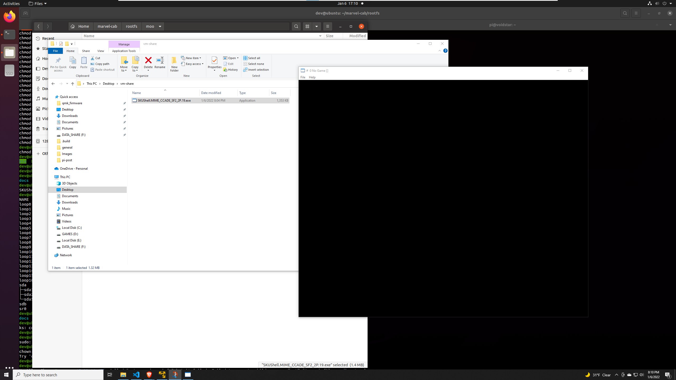
It runs! Apparently, this was a build artifact that the author didn't realize was on the system; he reached out to me about it on Twitter, and we had a great conversation about reverse engineering/emulation.
With the methods outlined in this post, we can now read and write the SPI flash to and from a USB drive using UBoot. We have extracted the root filesystem and identified the core emulation components. Our next steps will be to reverse engineer some of the binaries on this target to determine how difficult it will be to run custom firmware.
Conclusion / Next Steps
With this blog entry, we reviewed how to perform an initial teardown of an embedded device and identify potential debug headers using our multimeters/logic analyzers. We then reviewed how to analyze unknown UART traffic and connect to a serial port using screen with a Raspberry Pi. After connecting to the serial port, we discovered that the UBoot console could be accessed by pressing Ctrl-C. After reviewing the UBoot console, we wrote a depthcharge script to extract each SPI flash partition to an external flash drive. In our next post, we will take an in-depth look at the UBoot binary and learn how to create and modify memory maps using Ghidra; we will then attempt to flash a custom kernel to the device and see if we can install custom firmware.
All of the scripts and tools used can be found on github.
Thank you for taking the time to read this; if you have any questions or comments, please feel to reach out to me on Twitter!
If this kind of work is interesting to you and you would like to learn more, consider our hardware hacking bootcamp. This is a five-day course that is offered remotely and on-site; all hardware is shipped to your door and is yours to keep after the course! See our training page for more details. Our newsletter is also a great way to stay informed on new courses, tools that we are using, blog posts, and upcoming course offerings.