On the Road at the Leahy Center: Our first in-person training of 2022!
Overview
May of this year marked the first in-person training of 2023. This training took place at the Leahy Center for Digital Forensics and Cybersecurity.. The training was given to the IoT analysis team at the Leahy center, to improve the students' skills working in the field of IoT device analysis and research. In mid-May, I packed up and drove up to beautiful Burlington, Vermont, to spend a week with students hacking hardware.
In the large black case are the kits for each student, containing all their tools and targets.
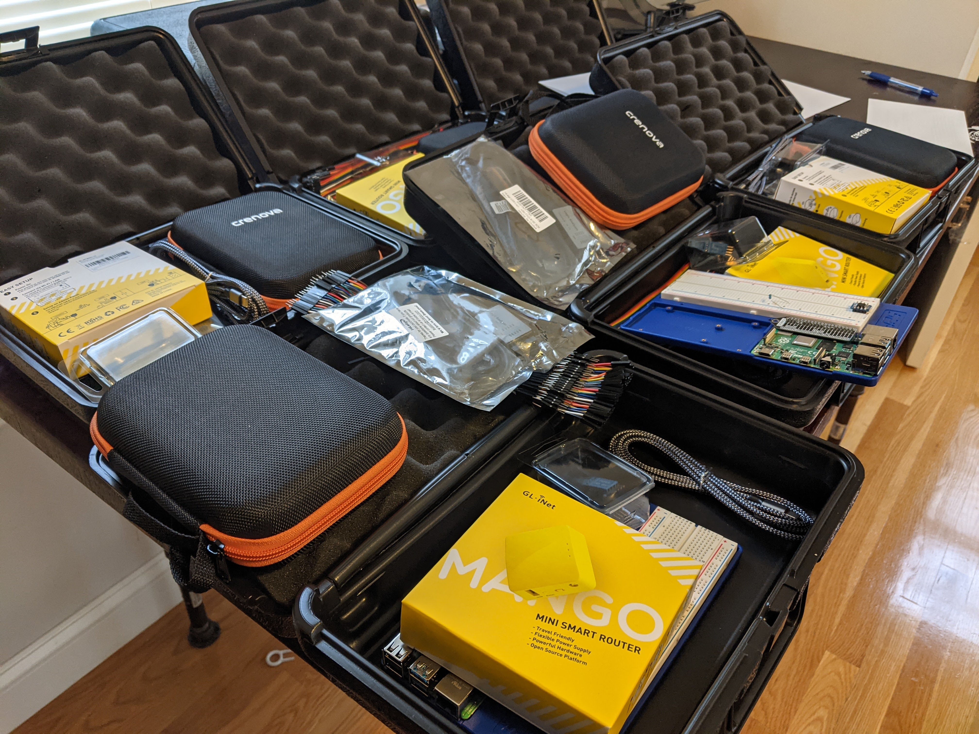
With a car full of targets and hardware tools, I showed up at the Leahy Center Monday morning, ready to spend the week hacking hardware.

Module 1: Tool Review and Fundamentals
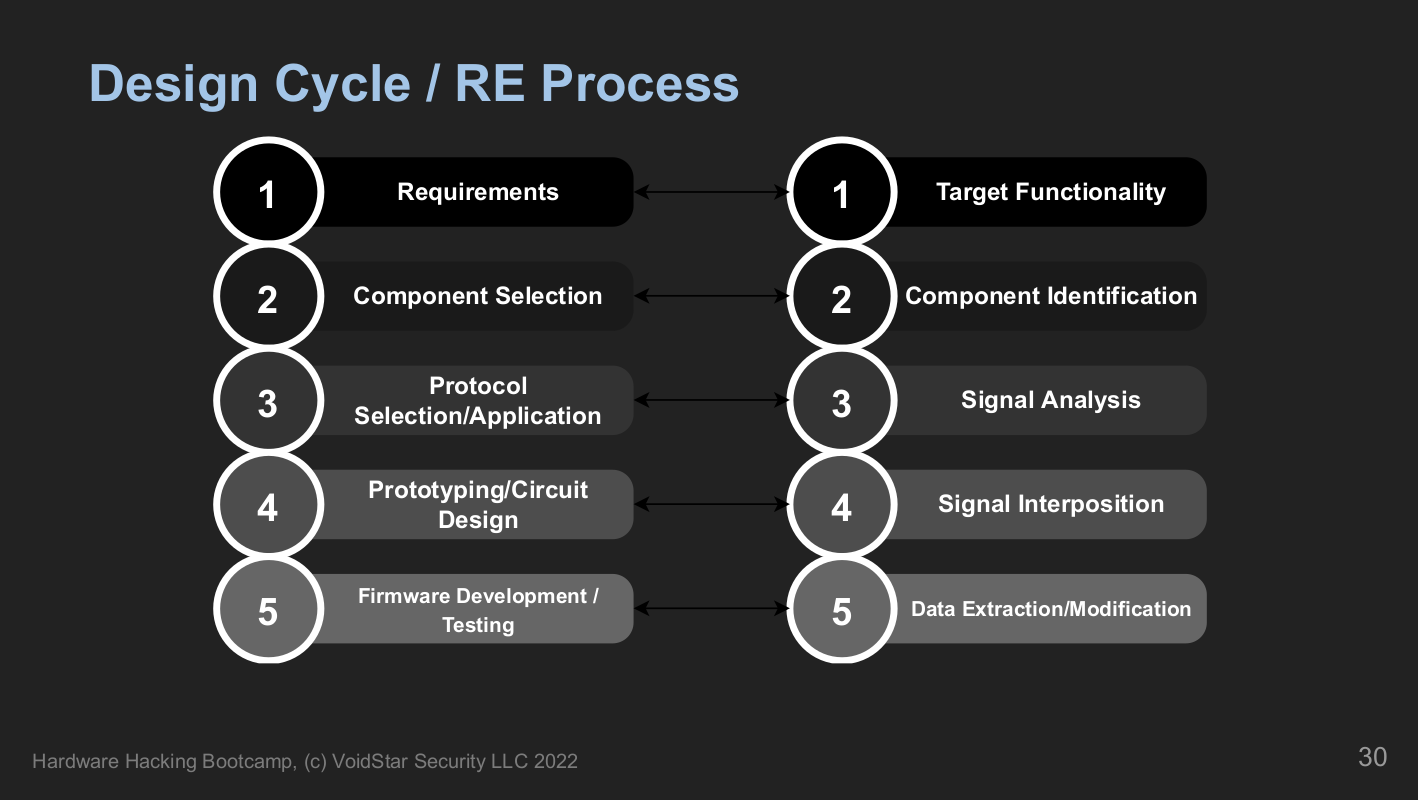
Module one is about giving students an overview of what hardware hacking is and where to start. Similar to how software reverse engineering works, where we break down the compiled bytecode into assembly instructions and work our way back up, we do the same with hardware. Starting with a review of how embedded systems are designed and the fundamentals of electricity. We end this segment with a five-phase approach to analyzing embedded systems:
After a brief review of fundamentals, we discuss how printed circuit boards are made and designed, using one of our targets as an example. Finally, students will analyze the first target and point out anything interesting based on what we learned during the PCB analysis section.
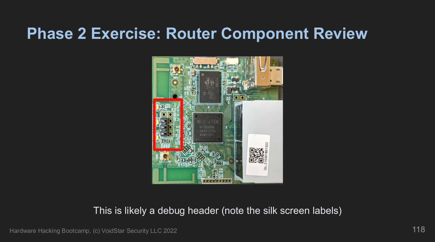
After we reviewed how PCBs are designed, we asked, "How do we know what components to focus on?". Next, we covered the various component types and how to identify them. We reviewed component types and their different packages early in the course because one of the first (and very understandable) questions often asked is:
How do I know what to look for or what I'm looking at when I open up a new device?"
After reviewing component types, students revisited the first platform armed with new knowledge about what to look for and what might be important. Next, we documented the components of interest and began our datasheet search.
Once we identified our components of interest and potential target points, we then learned how to measure the fundamental features of these devices, such as voltage, current, resistance, etc. Next, we covered the tools that we used to probe our five targets throughout the week, including:
- Multimeters
- Logic Analyzers
- Single Board Computers
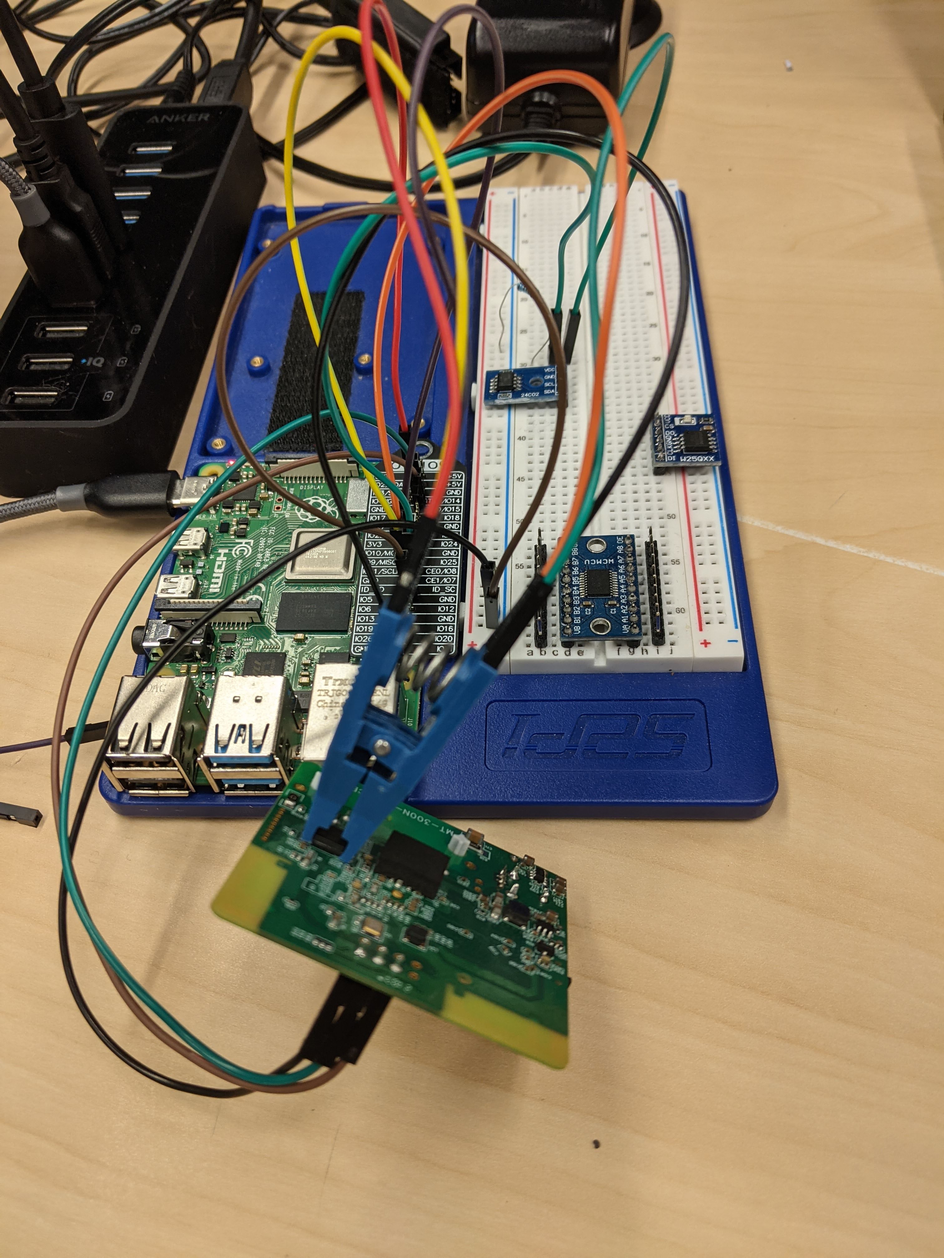
Throughout the week, students used their single-board computers (in this case, a Raspberry Pi) to perform hardware-level attacks on their targets. The Pi has been outfitted with a web interface, including Jupyter notebooks for each protocol reviewed:
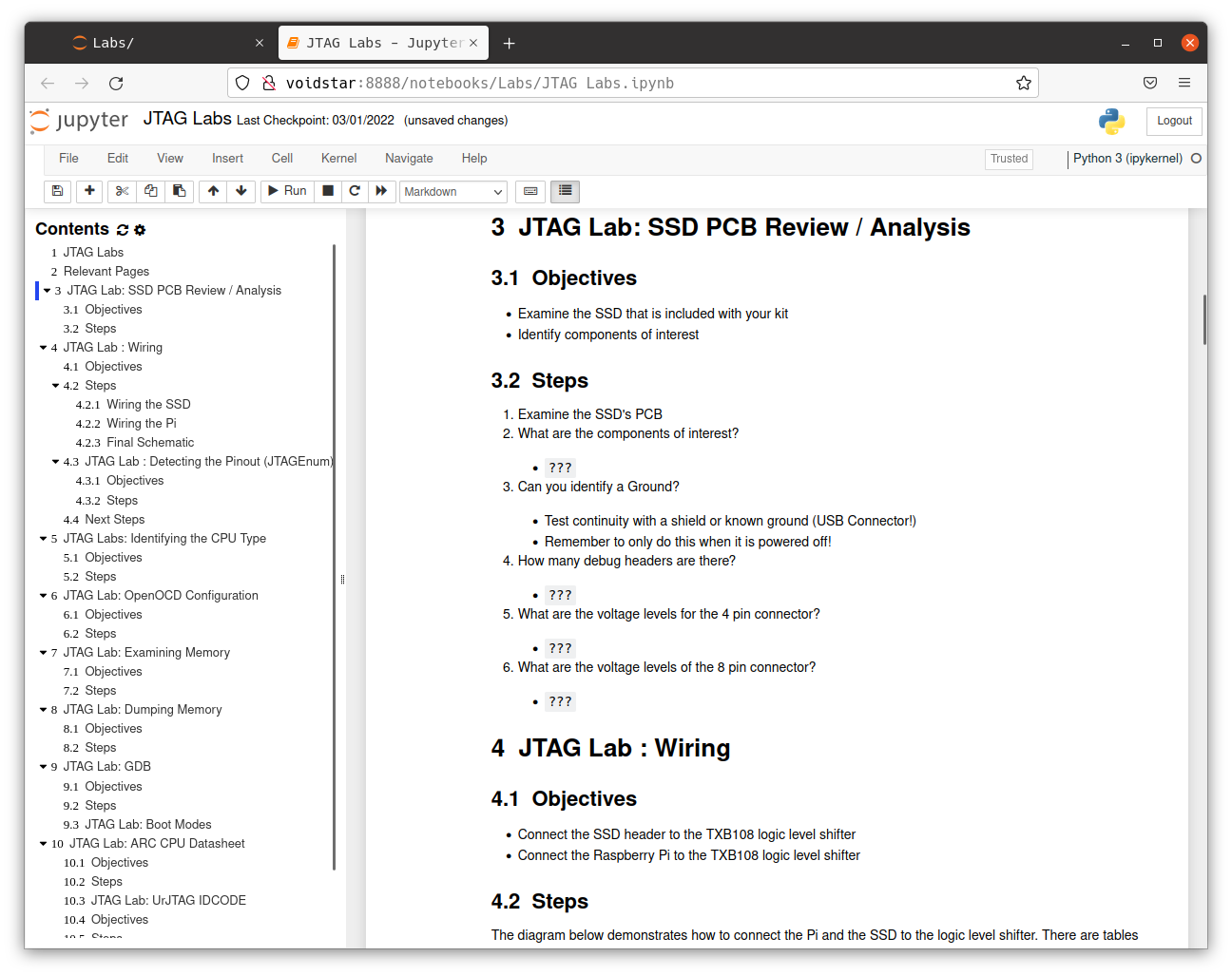
Using these tools, we learned more about our first target, measuring voltages on the various test pads and testing for continuity on some components of interest. After investigating one debug header, students noticed a voltage fluctuation on startup; next, we discussed UART. This is our first protocol segment; for each protocol segment, we performed the following:
- Learn how the protocol works at the signal level
- Analyze, decode and reverse engineer protocol traffic using lab exercises
- Learn how to approach the specific protocol as a reverse engineer via lab exercises
- Develop and use open-source tools for interfacing with this protocol
- Apply points 1-4 on the target device
Module 2: UART
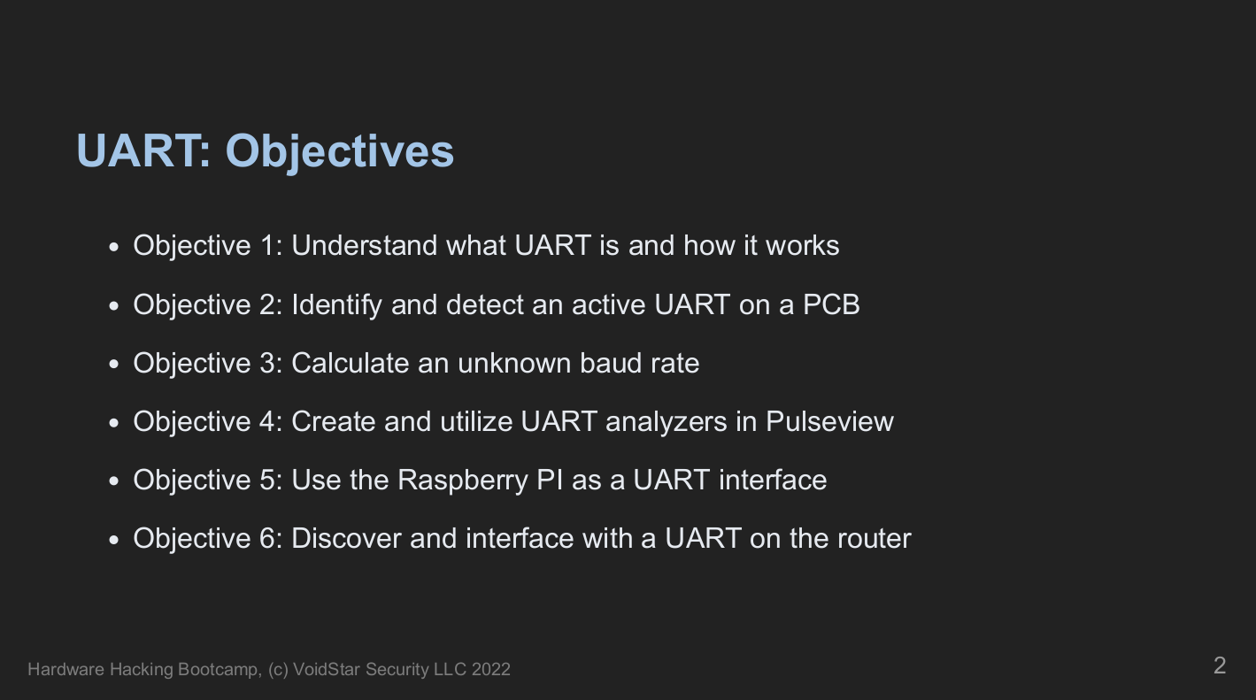
In the UART segment, students learned to identify a UART, capture traffic using a logic analyzer, and calculate the baud rate. Next, they interfaced with the target using minicom and screen. Students analyzed the data, which gave us an indicator of what day two had in store.
Module 3: U-Boot
Following our discovery of a UART and some exciting traffic, our second day started with a deep dive into the U-Boot bootloader. First, we reviewed some common bootup sequences used by embedded systems, covering definitions such as boot ROMs, SBL (secondary bootloaders), and U-Boot.
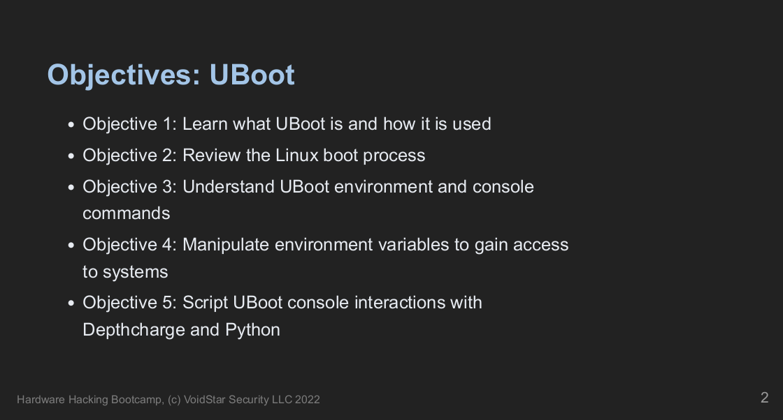
Understanding how the U-Boot bootloader can manipulate the underlying operating system is crucial. Therefore, we talked about the history of U-Boot, its structure, and how to approach/attack a U-Boot-based system as a reverse engineer.
For an introduction to U-Boot, students were given two QEMU virtual machines and asked to answer the following questions:
- What is the
bootcmd? - What are the kernel boot arguments?
- Can you change the boot arguments?
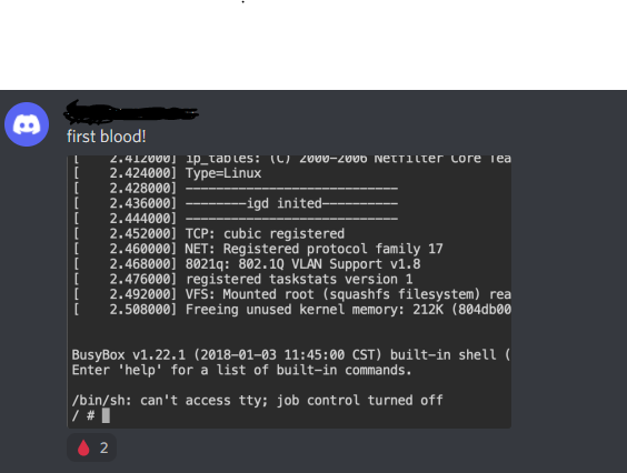
- Can you get access to a root shell?
After the virtual machine exercises were complete, we moved back to our router, armed with new knowledge of what to look for and what they might be able to modify; students attempted to answer similar questions to those answered before. However, this time they will notice that the environment is slightly different.
Upon investigating the routers' U-Boot environment, students discovered it was very different from their previous examples. There were some new commands in this environment; however, we spent some time exploring the spi command.
UBOOT> # help spi
spi spi usage:
  spi id
  spi sr read
  spi sr write <value>
  spi read <addr> <len>
  spi erase <offs> <len>
  spi write <offs> <hex_str_value>
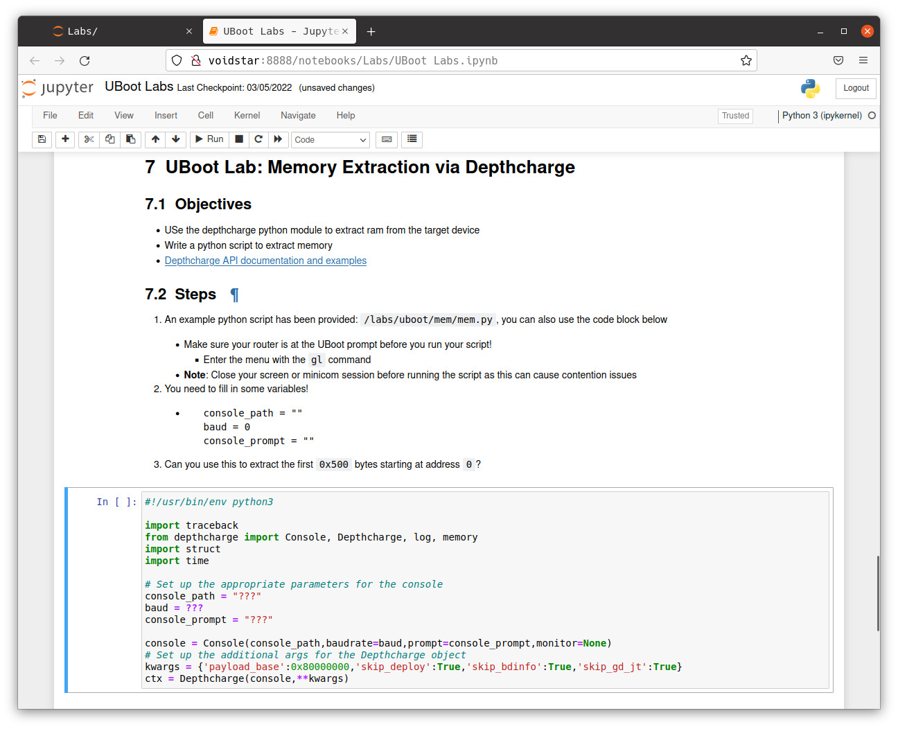
Students then learned about the depthcharge toolkit, a valuable tool for auditing U-Boot environments. Using depthcharge, a script was developed that allowed memory to be read to a file.
Despite depthcharge being able to extract the flash image from our target partially, we needed to learn more about the SPI protocol. In the next segment, students learned how SPI works at a low level by analyzing logic captures.
Module 4: SPI
Throughout this segment, students learned how the SPI interface works at the signal level and how these signals are used to generate packets. Students performed traffic and signal analysis throughout several labs and developed tools to interact with a SPI peripheral directly using the Raspberry Pi. We then covered practical applications of the SPI interface with regard to EEPROMs by analyzing a logic capture from an active SPI bus.
After learning more about how the protocol works (and, more importantly, the problems arising when using it), students utilized open-source tools to extract flash chips and wrote their own tools; armed with these tools, students attempted to extract the flash from their routers. However, this extraction was more difficult than anticipated. Students were introduced to bus contention and needed to find a way to read the SPI flash in-circuit.
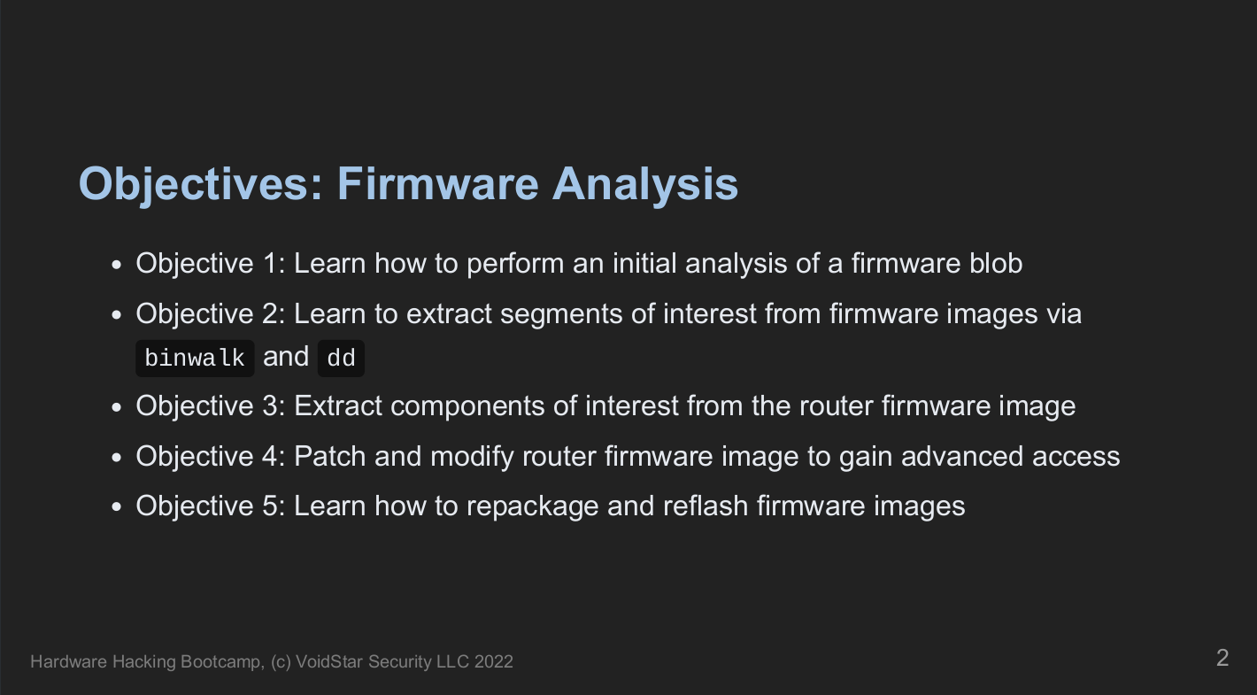
Module 5: Firmware Extraction and Unpacking
The goal of working on the router is for students to get access to a root console. Next, they began to search for the kernel arguments. After using binwalk to analyze the image, students used the binwalk results to manually extract the image's core components using dd.
We reviewed the Linux boot process, including examples of how kernel arguments can be passed to the kernel and the general boot flow for a Linux-based embedded system. Finally, students learned about device trees, their purpose, and how to compile/decompile them. I ran out of whiteboard space during this segment, but luckily, the walls made for an excellent substitute!

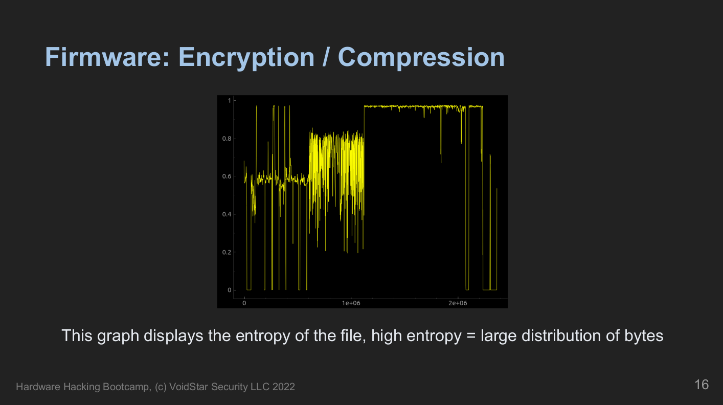
During this segment, we talked about various example firmware formats and discussed standard tools and techniques for analyzing an unknown binary. In addition, we reviewed entropy analysis, identifying interrupt vector tables, and how to handle various compression algorithms commonly used in firmware images.
Students will manually extract decompressed and modified segments of the firmware image to add a root console that will appear on boot. Once they had made their modifications, they repackaged and restructured a new firmware image to flashback to the target.
Module 6: I2C
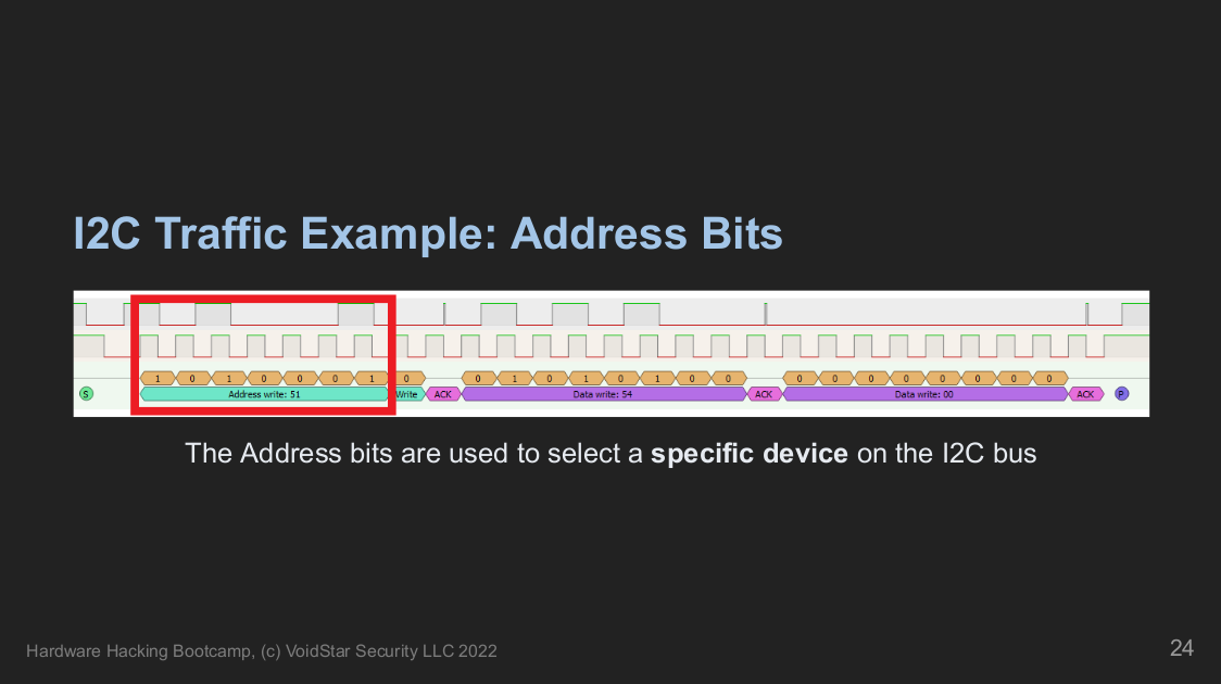
On day four, we moved on to another target, which required us to learn more about how the Inter-Integrated Circuit (I2C) protocol works at a low level. From here, students learned how to approach an I2C bus as a reverse engineer, about tools and techniques to interrogate the bus, and learn more about the devices connected to it. Open-source tools for probing various types of I2C devices are covered and used, and students wrote their own tools using Python.
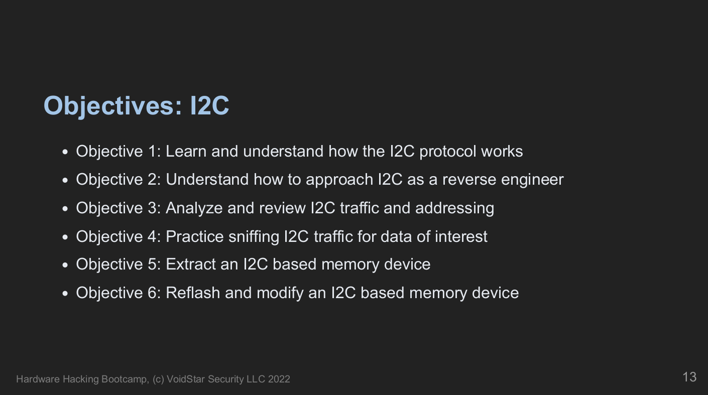
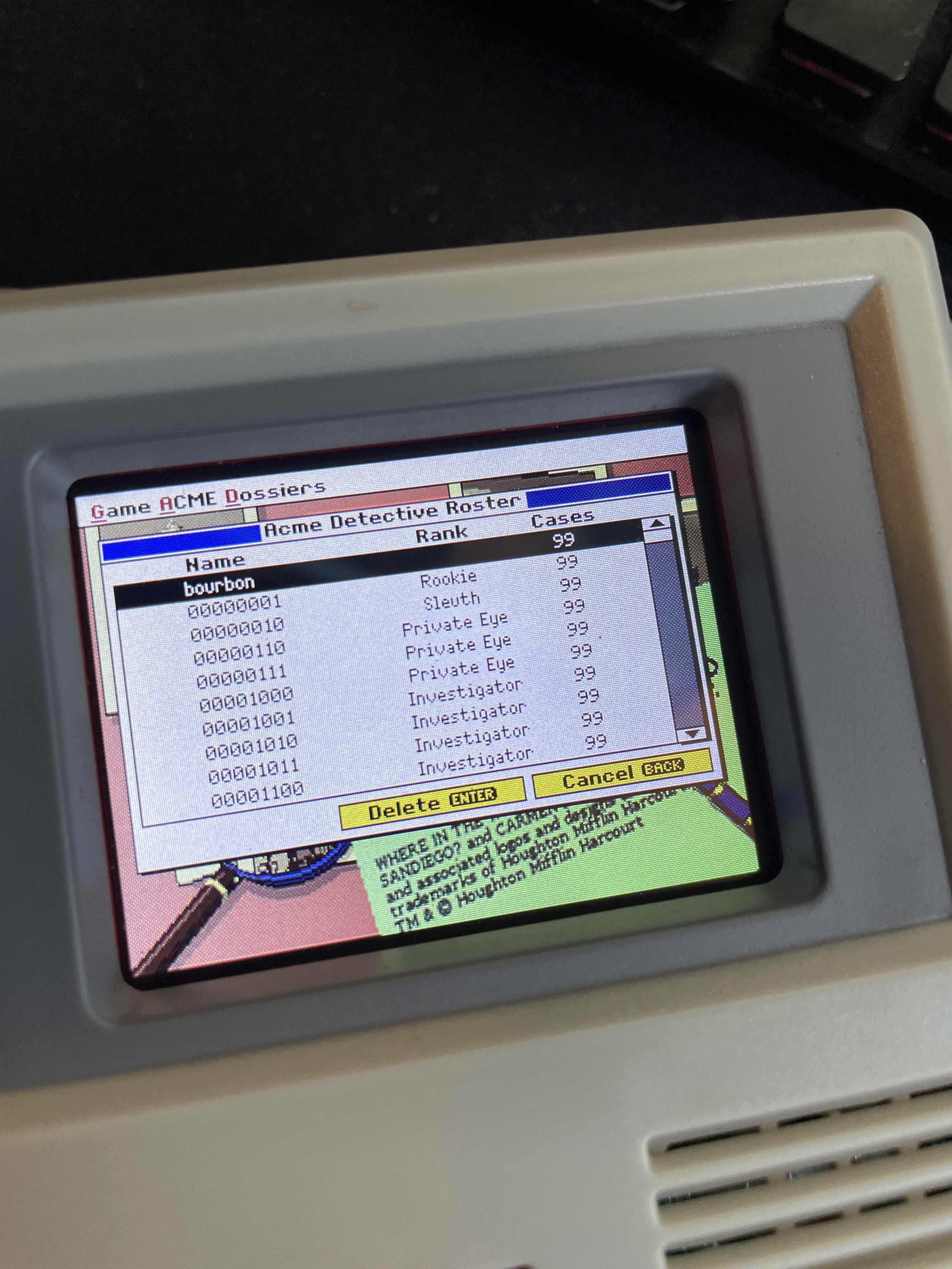
Students extracted and modified I2C-based EEPROMs, hacking their games to get a high score!
After understanding the protocols and the available tools, two different flash chips were extracted from one of their targets. After analyzing the resulting data and determining its structure using the techniques covered on day three, modified data was written back to the target. Students tested their custom tools and understanding of the data. Upon startup, the cabinet had been hacked by a rogue detective displaying the following data:
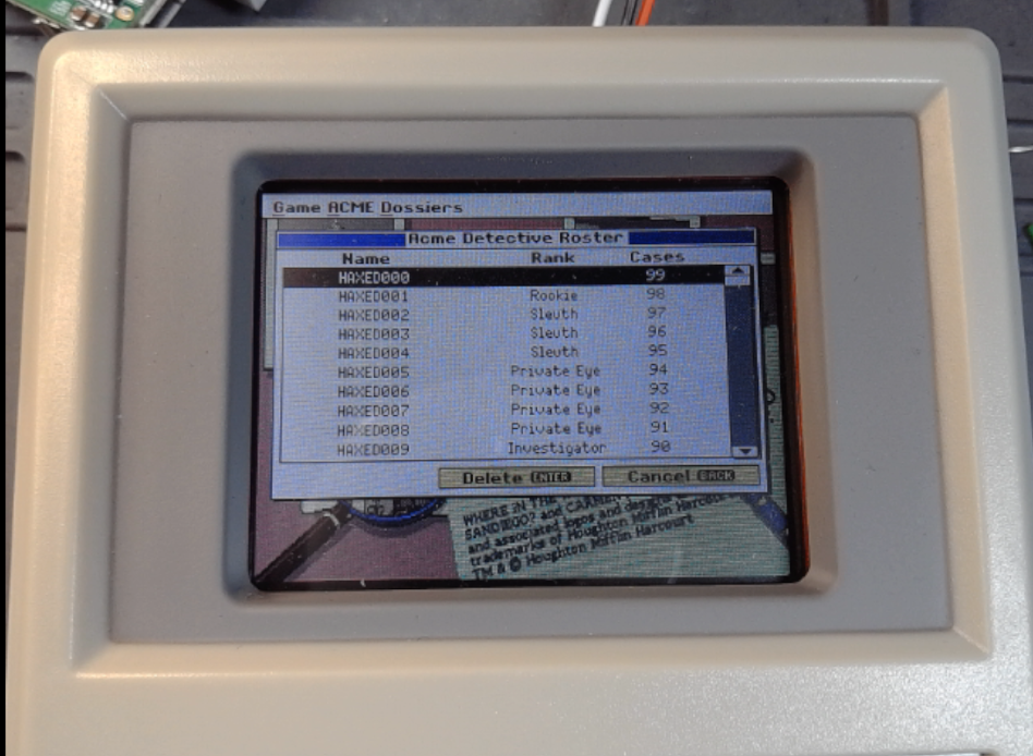
Students then patched and reflashed the data. However, they quickly learned that the data was harder to patch than they initially assumed. Next, students must figure out the custom binary format and checksum scheme; otherwise, their information is corrupted and deleted! However, they took the top spot when they determined the correct format for the flash image!
Module 7: JTAG
Next, we examined a new target in our kit; after surveying the target and testing for our previously understood protocols with no luck, we assumed we were dealing with a potential JTAG interface.

Students learned how the JTAG state machine works and how to take advantage of this state machine when reverse engineering an unknown JTAG TAP.
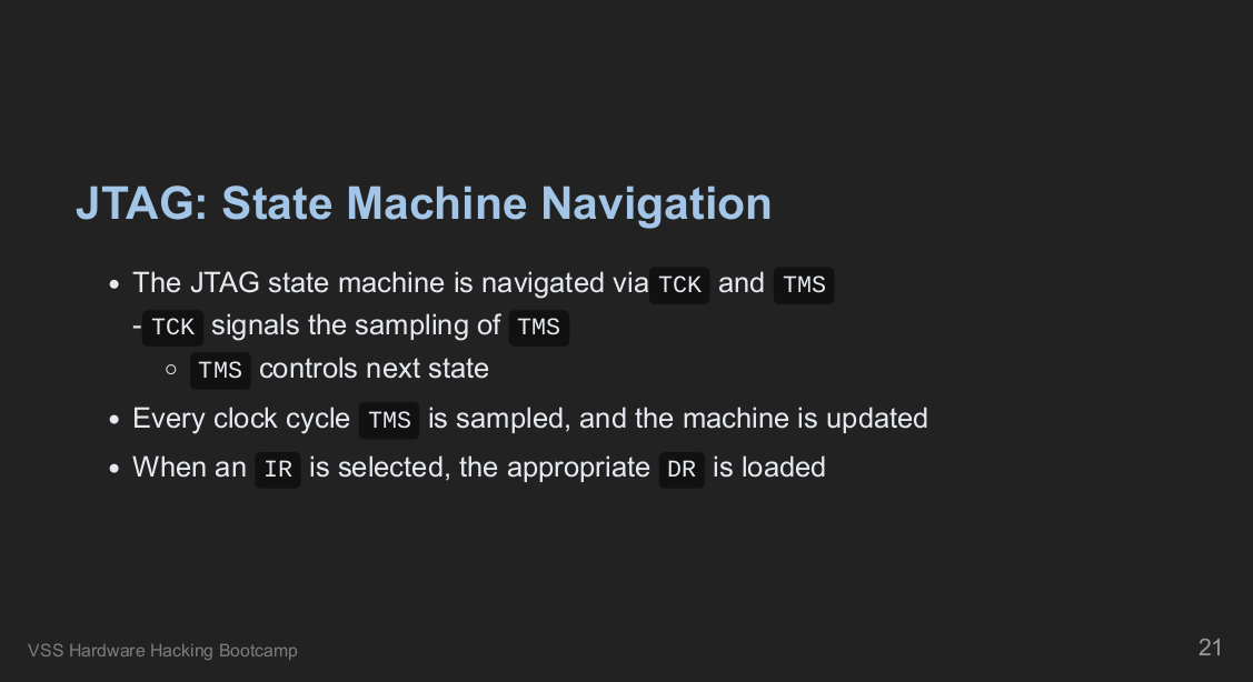
Similar to the previous labs, we built on the fundamental components outlined in the specification and covered how to brute force unknown JTAG pin assignments using the Raspberry Pi.

Throughout the JTAG segment, students manually navigated the scan chain and wrote custom config files for OpenOCD. Using these methods, students extracted memory, set breakpoints, and took total control over the target's execution flow.
SWD
One of the last targets in the kit is an ARM-based embedded device; students were tasked with analyzing the device using all of the techniques learned throughout the week. After performing a teardown and initial analysis, students found a new hardware-level debug interface - Single Wire Debugging (SWD). This module explained how this debug mechanism operates at the signal level and how we can leverage the ARM Debug Interface Specification to learn as much as possible about an unknown target.
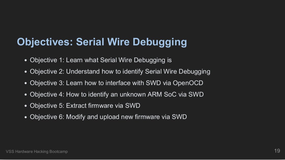
Throughout this final module, we developed an OpenOCD config file from the ground up and OpenOCD scripts to learn more about our target. We used the information we gathered using the ADI specification to learn how to attack our target further; this included learning how to extract and modify the device's internal flash to demonstrate that we've taken complete control. We also connected to the device using OpenOCD's GDB stub, allowing us to gain full control over the execution of the device!
Bonus Targets
For a final exercise, students were given a brand new target, which used multiple protocols covered in the course, and students were tasked with learning as much about the target as possible. Students broke up into groups and used what they learned throughout the week to attack their new targets. The targets can be seen in the image below:
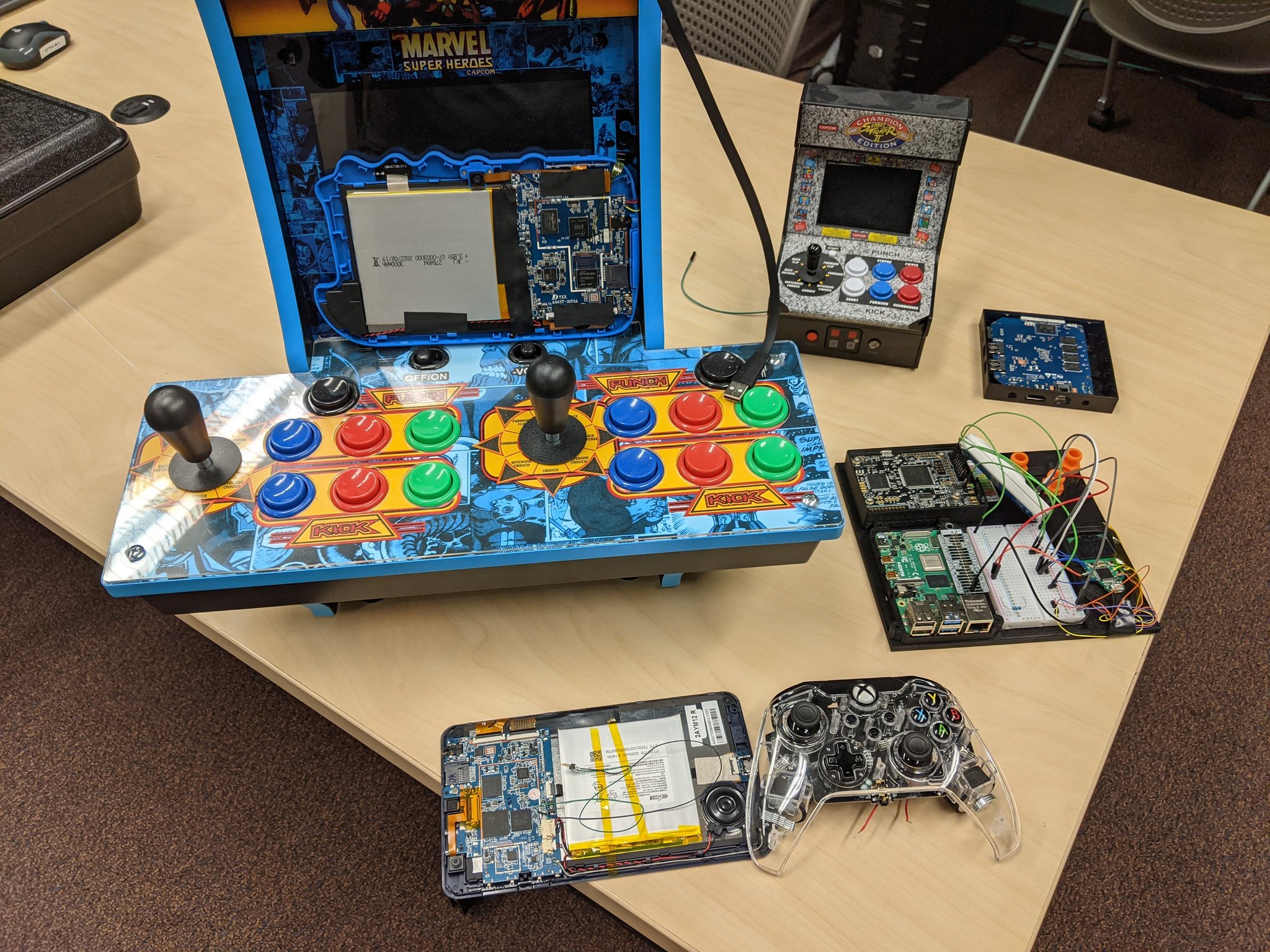
These new targets all came with different goals, including:
- Decoding button presses via I2C traffic captures
- Using Depthcharge / U-Boot scripts to extract the flash from a target
- Examining USB traffic to control/modify a target
Students took turns looking at the final new targets, learning how to apply what they learned throughout the week and using their new hardware hacking skills:
Conclusion
The week at the Leahy Center was extremely fun and productive. It was great to be able to teach students on-site again. Over the week, students learned how to assess embedded systems and how these protocols work at the signal level. They also learned to develop their tooling and troubleshoot when other tools fail. I cannot speak highly enough about the work that the Leahy Center folks do; if you're interested in doing security research, DFIR, and IOT research, check them out!
I look forward to seeing the excellent research they produce in the future, and I can't recommend the department highly enough to those looking for new hires or interns!
As always, if you have any questions about the course or hardware reverse engineering in general, don't hesitate to contact us. If you're interested in staying up to date with our blog posts and upcoming courses, check out our mailing list. For more reading on hardware hacking and reverse engineering, check out our publications. Thanks for reading!