Brushing Up on Hardware Hacking Part 1 - PiFex Configuration
Overview
Whether performing a training exercise with a large group or consulting clients with embedded security needs, there is one question that I constantly receive:
How do you pick which devices to use when learning hardware reverse engineering?
This is a very reasonable question; with so many random embedded devices on the market, picking something easy to learn can be difficult. With this three part "brush-up" series, we want to give our readers examples of devices they can use to learn more about reverse engineering embedded devices. For each of these posts, we will provide links to the software used and (non-affiliate) links to the devices we are tearing down.
The first device in our series will be this electric toothbrush.

Our goal is to extract the firmware from the device and see if we can also get hardware-level debugging working on the target.
Pi-Gen + PiFex
For this series, we will use a Raspberry Pi as our hardware hacking multi-tool. While we will use the PiFex board, it will not be required for those following along at home. However, one thing that will need to be used is an SD card image with the appropriate software tools and utilities installed. For this, we'll be using the open-source tools in our PiFex software repo as well as the tool PiGen.
PiGen can generate Raspberry Pi images; we will use this to create an SD card image based on the latest Raspbian OS version containing all required software for hardware-level reverse engineering.
Building an image with PiGen goes through multiple stages, each responsible for configuring different portions of the resulting image. Our modifications will be performed in stages one, two, and three.
In stage one, we modify the config.txt file to enable the various hardware peripherals that we will be using. This includes UART, SPI, I2C, and the DWC2 gadget driver for presenting an Ethernet device over USB.
# Modifications to config.txt
[all]
dtparam=i2c_arm=on
enable_uart=1
# PiFex Enable I2C Screen
dtoverlay=i2c6
# Set up USB Ethernet driver
dtoverlay=dwc2
We will modify the kernel command line in stages one and two to enable the i2c-dev kernel module.
# Modifications to cmdline.txt
console=serial0,115200 console=tty1 root=ROOTDEV rootfstype=ext4 fsck.repair=yes modules-load=dwc2,i2c-dev rootwait
# Modifications to 07-resize-init.diff
--- stage2.orig/rootfs/boot/firmware/cmdline.txt
+++ stage2/rootfs/boot/firmware/cmdline.txt
@@ -1 +1 @@
-console=serial0,115200 console=tty1 root=ROOTDEV rootfstype=ext4 fsck.repair=yes modules-load=dwc2,i2c-dev rootwait
+console=serial0,115200 console=tty1 root=ROOTDEV rootfstype=ext4 fsck.repair=yes modules-load=dwc2,i2c-dev rootwait quiet init=/usr/lib/raspberrypi-sys-mods/firstboot
During stage three, we will do the following:
- Install PiFex software dependencies
- Set up a
pifex-envvirtual environment containing the tools needed to access the OLED and other peripherals - Install various dependencies and tools for common hardware hacking utilities
- Set up a
- Enable systemd services to automatically launch our desired programs on boot; these include:
OLED.service: Used to drive the OLED screen, displaying the IP address of the Raspberry Pijupyter.service: Launches the Jupyter notebooks included in the PiFex repositoryopenocd.service: Launches the OpenOCD web interfacegadgets.service: Configures and enables the serial and Ethernet gadgetsserial-getty@ttyGS0.service: Spawns a login shell on the virtual serial device
You can enable our modifications as shown below:
# Clone the PiGen Repository
git clone https://github.com/RPi-Distro/pi-gen.git
# Clone the PiFex software repository
git clone https://github.com/voidstarsec/pifex-sw
# Copy the necessary PiFex files into the PiGen repository
# First, copy the config file
cp pifex-sw/pi-gen/pifex-config pi-gen/
# Copy the stage 1 files
cp pifex-sw/pi-gen/stage1/00-boot-files/files/config.txt pi-gen/stage1/00-boot-files/files
cp pifex-sw/pi-gen/stage1/00-boot-files/files/cmdline.txt pi-gen/stage1/00-boot-files/files
# Copy the stage 2 files
cp pifex-sw/pi-gen/stage2/01-sys-tweaks/00-patches/07-resize-init.diff pi-gen/stage2/01-sys-tweaks/00-patches/
# Copy the stage 3 files
cp pifex-sw/pi-gen/stage3/00-packages pi-gen/stage3/00-install-packages/
cp pifex-sw/pi-gen/stage3/01-run.sh pi-gen/stage3/00-install-packages/
# Copy the pifex-sw directory to stage3
mkdir pi-gen/stage3/00-install-packages/files/pifex/
cp -r pifex-sw pi-gen/stage3/00-install-packages/files/pifex/
cd pi-gen
./build-docker.sh -c pifex-config
The resulting image in the deploy directory will have all the necessary tools installed and some additional features to help streamline access to the Pi. One of the most helpful features is adding a custom USB gadget for serial and Ethernet connections to the Raspberry Pi. This way, users can access the Pi via the USB to serial device or the USB to Ethernet device that will be presented.
On first boot, the image will resize the root file system to match the remaining size of the SD card, and after that, you should see the following devices appear when the Pi is connected:
[337764.359794] usb 1-10.1.3: new high-speed USB device number 34 using xhci_hcd
[337768.528839] usb 1-10.1.3: device descriptor read/64, error -71
[337768.725882] usb 1-10.1.3: New USB device found, idVendor=0421, idProduct=1410, bcdDevice= 1.00
[337768.725900] usb 1-10.1.3: New USB device strings: Mfr=1, Product=2, SerialNumber=3
[337768.725905] usb 1-10.1.3: Product: nothing
[337768.725909] usb 1-10.1.3: Manufacturer: nobody
[337768.725913] usb 1-10.1.3: SerialNumber: 1000000097e25cab
[337768.733979] cdc_ether 1-10.1.3:1.0 usb0: register 'cdc_ether' at usb-0000:00:14.0-10.1.3, CDC Ethernet Device, 02:00:97:e2:5c:ab
[337768.735419] cdc_acm 1-10.1.3:1.2: ttyACM0: USB ACM device
[337768.765475] cdc_ether 1-10.1.3:1.0 enx020097e25cab: renamed from usb0
From here, you can access the Pi via either the USB-to-Serial or USB-to-Ethernet gadget. The Ethernet gadget has been configured to use a static IP of 192.168.8.1. You can modify the script on the file system at /home/pi/pifex/gadgets.
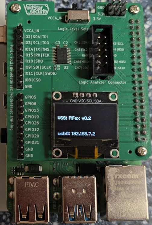
One of the services that gets set up is a basic network service that will display the IP address of the various connected interfaces on the screen of the PiFex; an example of this can be seen below:
The following services can be accessed over the network via the USB to Ethernet gadget or other network connections:
PiFex Services
Networking
As mentioned in the previous section, the Pi will present a composite serial device and Ethernet device over USB. The serial device can be accessed with tools such as minicom, putty or screen. The Ethernet device can be treated as a standard network interface.
# lsusb output
Bus 001 Device 034: ID 0421:1410 Nokia Mobile Phones nothing
The serial device can be accessed via screen as shown below:
sudo screen /dev/ttyACM0 115200
The OLED screen displays the IP addresses of any network interfaces currently configured. The default IP address for the USB to Ethernet gadget is 192.168.8.1. The web interface can be accessed by setting the presented interface to a static IP address in the 192.168.8.X range. This allows you to access all the PiFex features and software tools via USB.
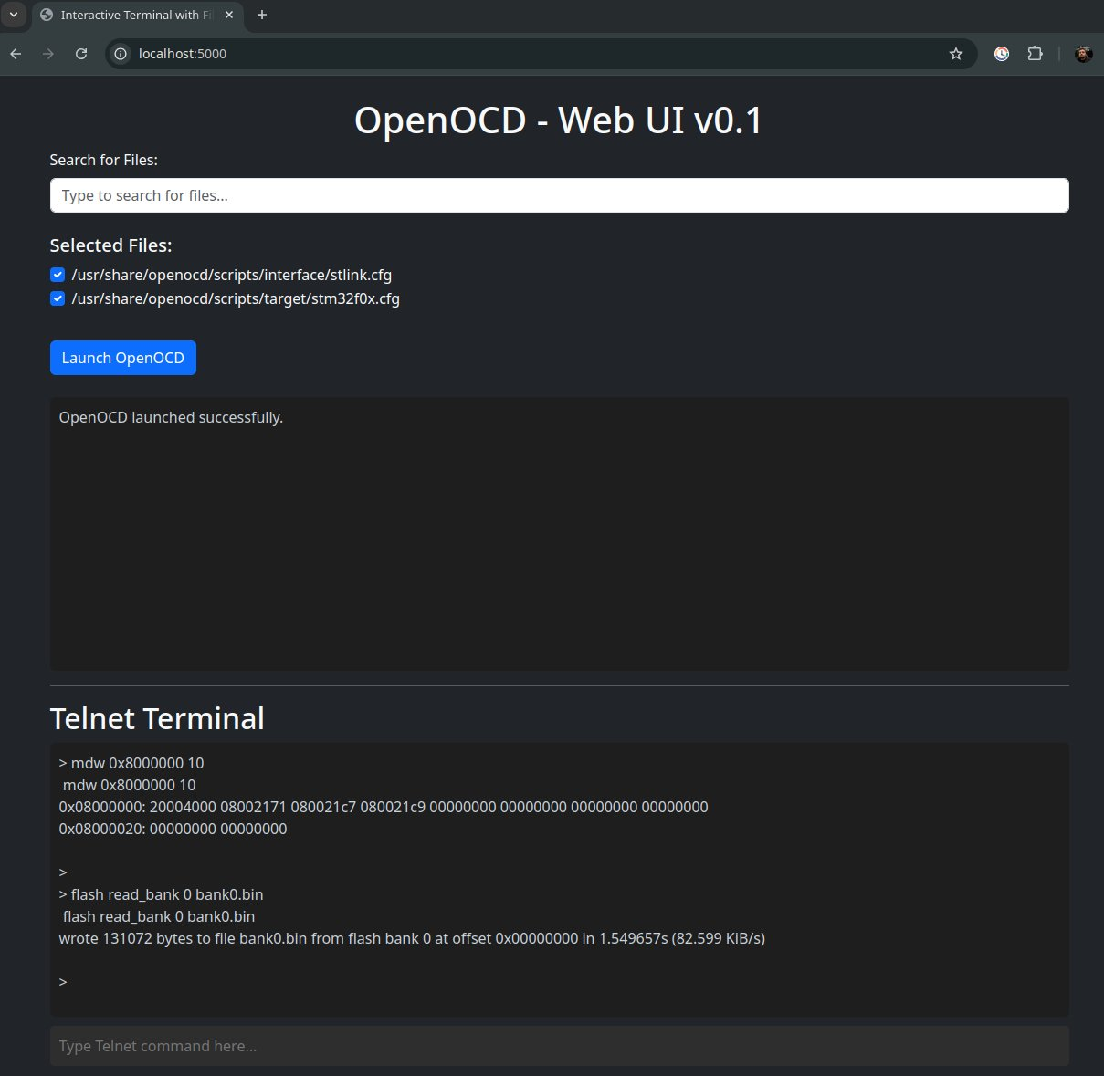
OpenOCD WebUI - Port 5000
I am currently developing a web-based interface for using OpenOCD. A beta version of this is included in the PiFex software repository.
The search bar at the top can be used to search for config files used by OpenOCD and includes an autocomplete feature:
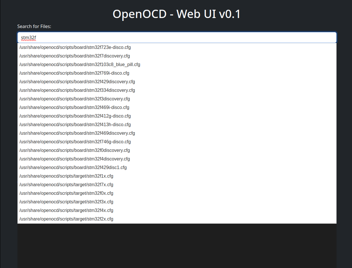
Once the desired configuration files are selected, OpenOCD can be launched and interfaced with via telnet and gdb.


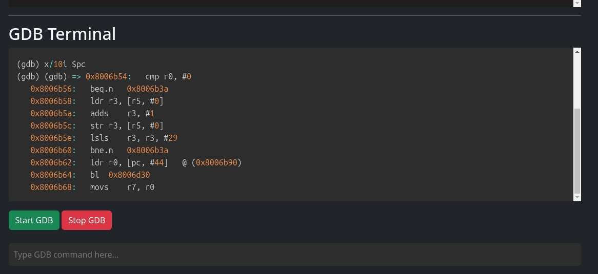
With OpenOCD launched, the GDB terminal and telnet interface can be accessed via the web browser:
There is also a memory-view feature that allows users to dump segments of memory via the UI:
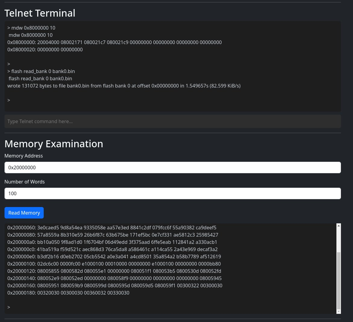
Note: This is a WIP interface, so feel free to provide feedback or submit PRs for desired features!
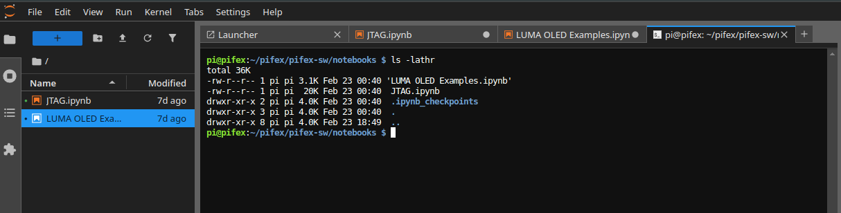
Jupyter Notebooks - Port 8888
The PiFex software repository includes Jupyter notebooks that demonstrate how to interact with the OLED interface and JTAG peripherals.
If you are prompted to set up a password/token, the token can be accessed by running the following commands on the Pi:
(pifex-env) pi@pifex:~/pifex/pifex-sw/pifex-ui $ systemctl status jupyter.service
● jupyter.service - Jupyter Notebook Startup
     Loaded: loaded (/lib/systemd/system/jupyter.service; enabled; preset: enabled)
     Active: active (running) since Fri 2025-02-28 03:01:58 GMT; 2 days ago
   Main PID: 487 (start_jupyter.s)
      Tasks: 2 (limit: 1572)
        CPU: 3.892s
     CGroup: /system.slice/jupyter.service
             ├─487 /bin/bash /home/pi/pifex/pifex-sw/services/start_jupyter.sh
             └─538 /home/pi/pifex-env/bin/python3 /home/pi/pifex-env/bin/jupyter-lab --ip=0.0.0.0

Feb 28 03:02:06 pifex start_jupyter.sh[538]: [C 2025-02-28 03:02:06.089 ServerApp]
Feb 28 03:02:06 pifex start_jupyter.sh[538]:
Feb 28 03:02:06 pifex start_jupyter.sh[538]:     To access the server, open this file in a browser:
Feb 28 03:02:06 pifex start_jupyter.sh[538]:         file:///home/pi/.local/share/jupyter/runtime/jpserver-538-open.html
Feb 28 03:02:06 pifex start_jupyter.sh[538]:     Or copy and paste one of these URLs:
Feb 28 03:02:06 pifex start_jupyter.sh[538]:         http://pifex:8888/lab?token=b50371a08991935ae326cc328572ae165ea0994b823fa27a
Feb 28 03:02:06 pifex start_jupyter.sh[538]:         http://127.0.0.1:8888/lab?token=b50371a08991935ae326cc328572ae165ea0994b823fa27a
Feb 28 03:02:06 pifex start_jupyter.sh[538]: [I 2025-02-28 03:02:06.139 ServerApp] Skipped non-installed server(s): bash-language-server, dockerfile-language-server-nodejs, javascript-typescript-langserver, jedi-language-server, julia-language-serv>
Mar 02 21:01:57 pifex start_jupyter.sh[538]: [I 2025-03-02 21:01:57.227 ServerApp] 302 GET / (@10.0.0.65) 2.30ms
Mar 02 21:01:57 pifex start_jupyter.sh[538]: [I 2025-03-02 21:01:57.236 LabApp] 302 GET /lab? (@10.0.0.65) 2.89ms
Included in these notebooks are examples of how to interact with the OLED display:

We have also included basic JTAG notebooks, which were used in one of our previous blog posts

Users can also access a terminal window through Jupyter-Lab as well; this can be done via "File "-> "New "-> "Terminal "
The goal with the PiFex board and open-sourcing these software utilities is to help newcomers learn more about reverse engineering. These tools are very similar to what we use in our training programs and our self-paced courses.
Conclusion
With our Pi configured, we can look at our first target! Stay tuned for part two (releasing 3/14!) for more information. With this post, we have:
- Demonstrated how to configure a Raspberry Pi for basic hardware hacking
- Released multiple scripts and configuration files for usage with the PiFex including
- PoC OpenOCD Web Interface
- Example Jupyter notebooks for interfacing with JTAG and the OLED Screen
It should be noted that you do not need a PiFex board to utilize these tools, these will work perfectly find (aside from the screen of course) without the PiFex board.
In our next post, we'll start tearing down our first target and see if we can learn anything more about how the system works.
If you're interested in hardware security training at your organization, please don't hesitate to contact us. We also have a self-paced training available here
If you want to stay up to date on the official releases, new courses, and blog posts, sign up for our mailing list here.
Lastly - we still have some tickets available for our in-person training in 2025 at RingZero! Check that out here