Overview
This is part three of our three part Brushing Up series, if this is your first time reading this series, check out our previous articles below:
- Brushing Up on Hardware Hacking - Configuring the PiFex
- Brushing Up on Hardware Hacking Part 2 - SPI, UART, Pulseview, and Flashrom
In our last post, we began a hardware tear-down of an electronic toothbrush from AliExpress. We extracted the SPI flash, identified an active UART, and re-programmed the SPI flash to display custom images on the screen.
Unfortunately, that did not result in firmware extraction, so we need to look for other ways to extract the firmware from this device. In our previous hardware tear-down, we mentioned the presence of SWD test pads; these can be seen in the image below:
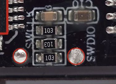
If you're a long-time reader of this blog or my other blog, this might look familiar to you. These two signals are used for something called Serial Wire Debug, or SWD, as we'll refer to it throughout the rest of this writeup. SWD was developed as an alternative to JTAG and also requires half as many pins. The next question is—how do we interface with this?
Note: For an introduction to SWD and how to approach it as a reverse engineer, check out our older blog post here
SWD and OpenOCD
Given that we have a part number for the MCU used on this target, we can refer to the datasheet to see if this chip meets the SWD specification. If this is the case, we can try to use OpenOCD to connect to this target and read out the internal flash memory.
If we check page 18 of the user manual we see the following:
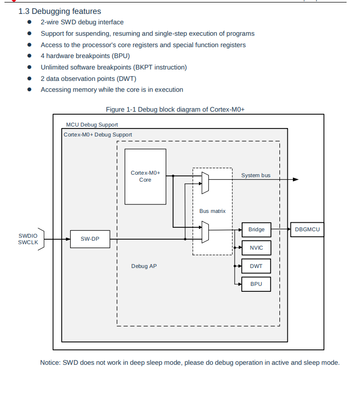
Based on this, we will assume that this confirms the ARM CoreSight specification and can continue trying to enumerate this device. If you're new to this space or have only ever worked with hardware-level debug interfaces as a developer, this might seem like a daunting task. Luckily for us, the open-source tool OpenOCD can be used to probe this interface, and we can run it on our Raspberry Pi. In this scenario we will use the Raspberry Pi as our debug adapter, and utilize the GPIO pins to communicate with the SWD interface on the micrcocontroller.
In the next section, we will review the basics of OpenOCD config files and how to write a basic template for an ARM Cortex target that uses SWD
OpenOCD Config Files
In order to communicate with this interface properly, we'll need two separate OpenOCD config files, one for the Raspberry Pi (our debugger) and one for our target (our debuggee). OpenOCD includes an example of using the Raspberry Pi as an SWD adapter, but we need to modify which pins we are going to use for SCLK and SDIO.
adapter driver bcm2835gpio
bcm2835gpio peripheral_base 0x20000000
bcm2835gpio speed_coeffs 113714 28

# Each of the SWD lines needs a gpio number set: swclk swdio
adapter gpio swclk -chip 0 9
adapter gpio swdio -chip 0 11

transport select swd

adapter gpio srst -chip 0 10
reset_config srst_only srst_push_pull
Now that we have the adapter side configured, we need to find an appropriate config file for our target microprocessor. One of the first things that you want to do when looking at a new CPU without the OEM (original equipment manufacturer) debugging tools is to check the list of supported OpenOCD config files. If we search for our part number, we find the following:
pi@pifex:~/targets/toothbrush/swd $ grep -ri BAT32* /usr/share/openocd/*
pi@pifex:~/targets/toothbrush/swd $
With no config files available, we have to write our own. While this might sound like a daunting task, it is actually not complex for an ARM Cortex M CPU. Using the STM32F0 as an example and following the guidelines on the OpenOCD website, we can generate our own, as shown below.
When writing a custom OpenOCD config files, there are two things one needs at a minimum:
- Debug Access Port (DAP) Definition A DAP is an interface on an MCU that allows access to the device's internals. It is typically part of the TAP (test access port), which is accessed via either JTAG or SWD.
- Target Definition
- This makes OpenOCD aware of the architecture of the chip, and which debug access port it is associated with
- Defining a target also gives us access some of the core features of the DAP (Debug Access Port) like memory access and debug level access
# Basic Config file for BAT32G MCUs

Source [find target/swj-dp.tcl]
source [find mem_helper.tcl]

# Define the name for our target chip, typically the part number
if { [info exists CHIPNAME] } {
   set  _CHIPNAME $CHIPNAME
} else {
   set  _CHIPNAME BAT32G135
}

# ONLY use ENDIAN with targets that can change it.
if { [info exists ENDIAN] } {
   set  _ENDIAN $ENDIAN
} else {
   set  _ENDIAN little
}

## Define the TAP ID; this can be gathered from the datasheet, but is not required for initial access
if { [info exists CPUTAPID ] } {
   set _CPUTAPID $CPUTAPID
} else {
   set _CPUTAPID 0x0bc11477
}

# swj_newdap is a function that will call `swd newdap` with the arguments that we provide here
swj_newdap $_CHIPNAME cpu -irlen 4 -ircapture 0x1 -irmask 0xf -expected-id $_CPUTAPID
# OpenOCD no longer automatically creates daps, so we need to make one ourselves
dap create $_CHIPNAME.dap -chain-position $_CHIPNAME.cpu

# Last we define the target, this requires a debug access port (dap) and the architecture of the device (cortex_m)
set _TARGETNAME $_CHIPNAME.cpu
target create $_TARGETNAME cortex_m -endian $_ENDIAN -dap $_CHIPNAME.dap
We can run OpenOCD with these two config files as shown below:
pi@pifex:~/targets/toothbrush/swd $ openocd -f raspberrypi-native.cfg -f swd-target.cfg
Open On-Chip Debugger 0.12.0
Licensed under GNU GPL v2
For bug reports, read
        http://openocd.org/doc/doxygen/bugs.html
srst_only separate srst_gates_jtag srst_push_pull connect_deassert_srst

Info : Listening on port 6666 for tcl connections
Info : Listening on port 4444 for telnet connections
Warn : An adapter speed is not selected in the init scripts. OpenOCD will try to run the adapter at the low speed (100 kHz)
Warn : To remove this warnings and achieve reasonable communication speed with the target, set "adapter speed" or "jtag_rclk" in the init scripts.
Info : BCM2835 GPIO JTAG/SWD bitbang driver
Info : clock speed 100 kHz
Info : SWD DPIDR 0x0bc11477
Info : [BAT32G135.cpu] Cortex-M0+ r0p1 processor detected
Info : [BAT32G135.cpu] target has 4 breakpoints, 2 watchpoints
Info : starting gdb server for BAT32G135.cpu on 3333
Info : Listening on port 3333 for gdb connections
Info : [BAT32G135.cpu] external reset detected
Info : accepting 'telnet' connection on tcp/4444
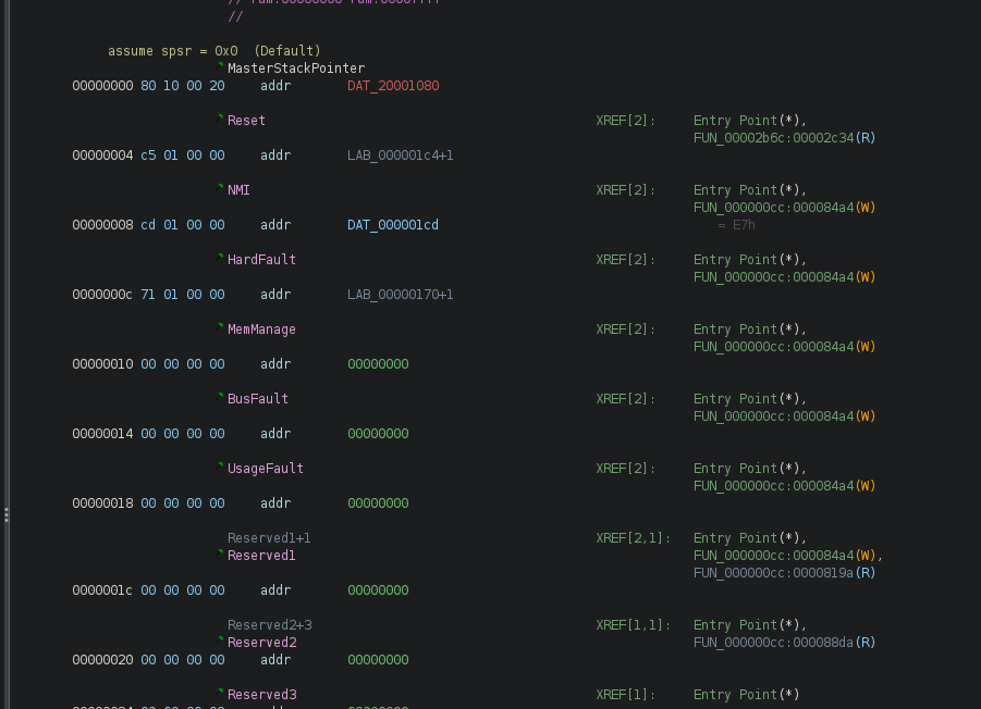
Success! We have a SWD connection. SWD (when adherent to the CoreSight specification) allows us to read memory, and given that the flash memory is mapped at a specific address, we should be able to read out the flash memory. We know from the datasheet that the internal flash is mapped at memory address 0x0 and is 64kb in size. We can confirm this by looking at memory at address 0, as shown below:
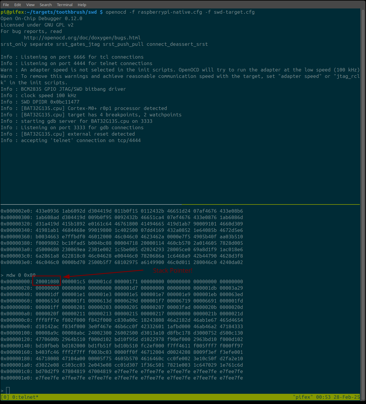
As you can see in the image above, the structure of the flash memory matches what we would expect to see in a Cortex M firmware image, with the first four bytes being a stack pointer, followed by what appears to be an IVT (interrupt vector table)
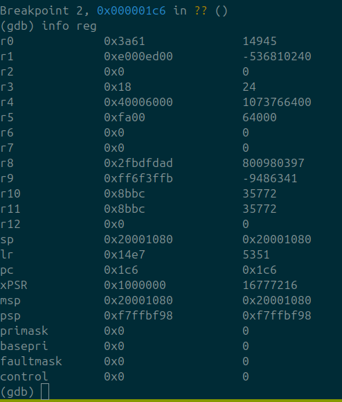
In addition to reading memory, we can connect via gdb and step through the firmware. This can be done by running gdb-multiarch and connecting to the exposed GDB port via
target extended-remote :3333
This results in us being able to set breakpoints, read registers, and step through individual instructions:
Next, we will dump the internal flash memory as well as the "data flash" using the dump_image command as shown below:
> dump_image toothbrush-firmware.bin 0 65536
dumped 65536 bytes in 2.449085s (26.132 KiB/s)
> dump_image data-flash.bin 0x500000 0x600
dumped 1536 bytes in 0.123736s (12.123 KiB/s)
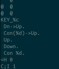
If we look through the firmware, we can see that we have some of the debug strings that we saw in the UART output. The data flash region contained no data.
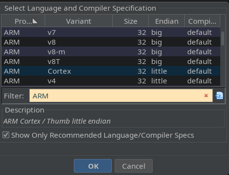
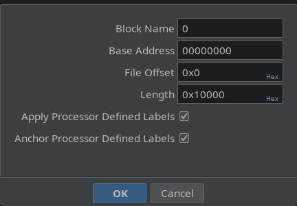
Now that we have extracted this MCU's internal flash memory using SWD, we can examine it in Ghidra to learn more about its functionality. We will specify the architecture as ARM Cortex little-endian and the load address as 0, as denoted in the datasheet.
When looking at a Cortex firmware image, it is always best to start with the IVT. We can see that Ghidra has already defined these for us. These values are used to handle interrupts and determine where the CPU should jump when an interrupt occurs. Pointers can be generated in Ghidra by hovering over the location of interest ant pressing p after generating pointers from the IVT. We have the following:
After creating these pointers, we can launch Ghidra's auto-analysis. There is not much code here, so Ghidra makes quick work of it. One of the first functions that stood out was the one responsible for printing the debug output that we monitored earlier. This function and its cross-references all make sense, which is a good sign that we have properly loaded the firmware image into Ghidra.
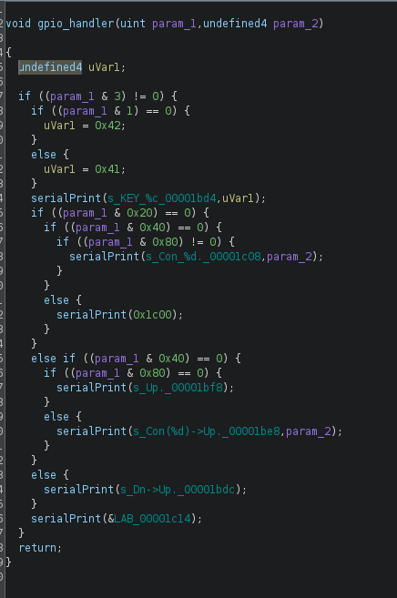
We can see that the function listed above is checking bit certain bits to be set in param_1 and is using that to determine which button was pressed. Once the appropriate bit has been detected in param_1, the firmware will then print debug output to the user (which we saw in part 2)
A fun PoC might be to make this handler print different statements. However, we have one problem, since OpenOCD does not support this chip, we cannot easily modify the internal flash without writing our flash driver. This can be a heavy lift for complex targets, but in our case, the example code included on the previously linked website for this chip include code for erasing and programming the flash
Using this as a template, we should be able to develop a flash programming "algorithm" for OpenOCD that will allow us to erase and re-program the flash. We will start with the erase function.
Flash Operations: An Overview
When working with a micro-controller, the flash memory is accessed via memory mapped IO. In order to reprogram or erase the micro-controller these registers must be accessed in a specific manner, which can be found in the datasheet. According to our datasheet we have the following registers that can be used to interact with the flash memory
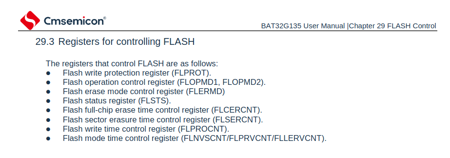
By interacting with these registers, we can perform flash erase and write operations.
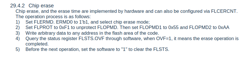
Flash Erase
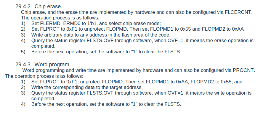
If our goal is to upload modified firmware, first, we must erase the flash. Flash cells can not be modified unless they are in the erased (0xff) state. If we look at the source files that are included with the SDK, we find an example of how to erase the flash:
int EraseChip (uint32_t adr)
{
    __DI;
    FMC->FLERMD = 0x08;
    FMC->FLPROT = 0xF1;
    FMC->FLOPMD1 = 0x55;
    FMC->FLOPMD2 = 0xAA;
    // Write data to start address of sector to trigger Erase Operation
    *(uint32_t *) adr = 0xFFFFFFFF;
    // polling OVER Flag
    while((FMC->FLSTS & FMC_FLSTS_OVF_Msk) == 0);
    FMC->FLSTS = FMC_FLSTS_OVF_Msk;
    FMC->FLERMD = 0x00;
    FMC->FLPROT = 0xF0;
    __EI;
    return(0);
}
This example code performs the operations described in the datasheet as shown below:
We can emulate this using OpenOCD's TCL scripts. If you are not familiar with TCL, the set command is used to create a variable. The mww commands are defined by OpenOCD and stand for Memory Write Word.
proc bat32_start_erase_flash {ADDR} {
    set FLERMD 0x4002000C
    set FLPROT 0x40020020
    set FLOPMD1 0x40020004
    set FLOPMD2 0x40020008
    mww $FLERMD 0x8
    mww $FLPROT 0xF1
    mww $FLOPMD1 0x55
    mww $FLOPMD2 0xAA
    mww $ADDR 0xFFFFFFFF
}

proc bat32_finish_erase_flash { } {
    set FLSTS  0x40020000
    set FLERMD 0x4002000C
    set FLPROT 0x40020020
    mww $FLSTS 1
    mww $FLERMD 0x00
    mww $FLPROT 0xF0;
}
With this (somewhat hacky) implementation, we can include this additional tcl file when running OpenOCD (with the -f option) and attempt erase the flash.
> halt
> bat32_start_erase_flash 0
> bat32_finish_erase_flash
> reset
[BAT32G135.cpu] clearing lockup after double fault
[BAT32G135.cpu] halted due to debug-request, current mode: Handler HardFault
xPSR: 0x61000003 pc: 0xfffffffe msp: 0x20001050
Polling target BAT32G135.cpu failed, trying to reexamine
[BAT32G135.cpu] Cortex-M0+ r0p1 processor detected
[BAT32G135.cpu] target has 4 breakpoints, 2 watchpoints
> mdw 0 0x100
0x00000000: ffffffff ffffffff ffffffff ffffffff ffffffff ffffffff ffffffff ffffffff
0x00000020: ffffffff ffffffff ffffffff ffffffff ffffffff ffffffff ffffffff ffffffff
0x00000040: ffffffff ffffffff ffffffff ffffffff ffffffff ffffffff ffffffff ffffffff
0x00000060: ffffffff ffffffff ffffffff ffffffff ffffffff ffffffff ffffffff ffffffff
It's erased, but how do we know this? The flash data that we previously read out with the dump_image command is now all 0xFFs, which is the erased state of the internal flash memory. Now that we have correctly implemented the erase function, lets move on to the write function. This will allow is to re-write the firmware image with some slight modifications.
Flash Write
The example code included in the SDK includes a function for programming flash memory. The code for programming the internal flash memory can be seen below:
int ProgramPage (uint32_t adr, uint32_t sz, uint8_t *buf)
{
    uint32_t i;
    uint8_t *ptr;
    ptr = (uint8_t *) adr;
    FMC->FLPROT = 0xF1;
    for(i=0; i<sz; i++)
    {
        __DI;
        FMC->FLOPMD1 = 0xAA;
        FMC->FLOPMD2 = 0x55;
        *ptr++ = *buf++;
        __EI;
        // polling OVER Flag
        while((FMC->FLSTS & FMC_FLSTS_OVF_Msk) == 0);
        FMC->FLSTS = FMC_FLSTS_OVF_Msk;
    }
    FMC->FLPROT = 0xF0;
    return (0);
}
We can see a detailed explanation of this in the user manual on page 737.
Thus far we have done a simple flash-erase implementation using the TCL scripting language included with OpenOCD. If you are familiar with TCL, you know that dealing with raw binary files can be difficult, to implement re-flashing the MCU, we will use the OpenOCD Python/Telnet API.
OpenOCD: Flash Read/Write in Python
We can use the available telnet client with modifications to re-flash the CPU. The full script for this can be found here, the example below contains two subroutines that will erase the chip and re-write the flash:
# Processor specific variables
FMC_BASE = 0x40020000
FLSTS  =                      FMC_BASE+0x00000000  # Flash status register                                      */
FLOPMD1 =                     FMC_BASE+0x00000004  # Flash operation mode register 1                            */
FLOPMD2  =                    FMC_BASE+0x00000008  # Flash operation mode register 2                            */
FLERMD    =                   FMC_BASE+0x0000000C  # Flash erase mode register                                  */
FLCERCNT  =                   FMC_BASE+0x00000010  # Flash chip erase control register                          */
FLSERCNT  =                   FMC_BASE+0x00000014  # Flash sector erase control register                        */
FLNVSCNT  =                   FMC_BASE+0x00000018  # Flash address setup time (Tnvs) control register           */
FLPROCNT  =                   FMC_BASE+0x0000001C  # Flash program control register                             */
FLPROT    =                   FMC_BASE+0x00000020  # Flash protect control register                             */
FLPRVCNT  =                   FMC_BASE+0x00000038  # Flash program recovery time (Trcv) control register        */
FLERVCNT  =                   FMC_BASE+0x0000003C  # Flash erase recovery time (Trcv) control register          */

def erase_flash(ocd,addr):
    ocd.writeWord(FLERMD,0x8)
    ocd.writeWord(FLPROT, 0xF1)
    ocd.writeWord(FLOPMD1, 0x55)
    ocd.writeWord(FLOPMD2, 0xAA)
    ocd.writeWord(addr, 0xFFFFFFFF)
    while(ocd.readByte(FLSTS)[0] != 1):
        time.sleep(.0001)
    ocd.writeWord(FLSTS, 1)
    ocd.writeWord(FLERMD,0)
    ocd.writeWord(FLPROT, 0xF0)
    ocd.send("reset halt")
    return

'''
Program the flash 0x200 bytes at a time
'''
g_start_addr = 0
def program_flash(ocd,prog_data,start_addr):
    global g_start_addr
    ocd.writeWord(FLPROT,0xF1)
    for x in range(0,len(prog_data)):
        print(f"Start Addr: {g_start_addr:X} Programming word {x:X} of {len(prog_data):X} - {prog_data[x]:X}")
        ocd.writeByte(FLOPMD1,0xAA)
        ocd.writeByte(FLOPMD2,0x55)
        ocd.writeByte(g_start_addr,prog_data[x])
        while(ocd.readByte(FLSTS)[0] != 1):
            time.sleep(.0001)
        ocd.writeByte(FLSTS,1)
        g_start_addr += 1
    ocd.writeByte(FLPROT,0xF0)
    return
if __name__ == "__main__":
    parser = argparse.ArgumentParser(description="BAT32 OpenOCD Reflash Utility")
    parser.add_argument("-o","--operation",action='store',type=str,help="Operation to perform, e = erase, f = flash",required=True)
    parser.add_argument("-f","--file",action='store', type=str,help="File to reflash")
    args = parser.parse_args()
    prog_data = []
    with OpenOcd() as ocd:
        if args.operation == 'f':
            if args.file != None:
                with open(args.file,'rb') as infile:
                    data = bytes(infile.read())
            # Erase target flash memory
            erase_flash(ocd,0)
            for page in range(0,FLASH_SIZE,0x200):
                pdat = data[page:page+0x200]
                program_flash(ocd,pdat,page)
            status_reg(ocd)
            clear_stack(ocd,0x20000000,0x20002000)
        elif args.operation == 'e':
            print("Erasing flash, please wait ... ")
            erase_flash(ocd,0)
After running this script and examining flash memory, we see the following:
# Dump image using telnet OpenOCD prompt
> dump_image reflashed.bin 0 65536
pi@pifex:~/targets/toothbrush/swd $ md5sum reflashed.bin
f1d5ad600a6d5d15564ae50018c7ffe9  reflashed.bin
pi@pifex:~/targets/toothbrush/swd $ md5sum toothbrush-firmware.bin
f1d5ad600a6d5d15564ae50018c7ffe9  toothbrush-firmware.bin
Success! We've successfully erased and re-programmed this micro-controller using OpenOCD. Next let's see if we can reflash a modified firmware image, as a quick test we will change one of the hard coded strings to print out "Hello World!" when a button is pressed.
The patches to the firmware image were made in a hex editor and reflashed as shown below:
python3 bat32utils.py -o f --file patched-firmware.bin
After reflashing this, we can check the UART to see if our patches worked - after connecting via screen we press a few keys and ...
DOWN
DOWN
DOWN
Hello World!
Success! We've properly reflashed the firmware with our modest patches.
The following steps for this work would be to implement the flash programming algorithm in C and recompile OpenOCD with support for this device. Given that this post series is already at nearly 8,000 words I think we are at a good stopping point!
I hope that you enjoyed reading this, and learned something new along the way. Go check your junk drawer and see if there are any potential targets for learning hardware hacking!
Conclusion
Who would have thought you could have this much fun with a toothbrush? I hope this post helped de-mystify some of the capabilities included with OpenOCD. With this post, we have covered the following:
- Enumerating an SWD peripheral with the PiFex/OpenOCD
- Writing basic OpenOCD config files for Cortex M devices
- Implementing flash memory erase/write algorithms using OpenOCD commands
This was all done with open-source software and the PiFex interface board. If you would like to purchase a kit that includes a PiFex board and an SD card with the PiFex image, we have a few kits in our shop here.
If you’re interested in hardware security training at your organization, please don’t hesitate to contact us. We also have a self-paced training available here
If you want to stay updated on the official releases, new courses, and blog posts, sign up for our mailing list here.