Tools and Series Overview
Overview
Recently on Twitter, I was approached with a request for a roadmap for learning how to reverse engineer embedded systems. This question is a common one and is one of the reasons that I developed our training course. But, since that is not accessible to everyone, I wanted to create a series of blog posts with the goal being to set people on the path to learning more about hardware hacking and reverse engineering. This series will focus on open-source tooling and (relatively) low-cost targets.
Like any reverse engineering project or skill-set, it is essential to focus on the fundamentals. We can think of our fundamental building blocks as various digital signals and protocols for the targets we will review in this series. This series of posts will review the following protocols and their relevant applications/tools.
- UART - Universal Asyncronous Receiver Transmitter
- UBoot
- Depthcharge
- SPI - Serial Peripheral Interface
- Flashrom
- I2C - Inter-Integrated Circuit
- i2cdetect
- i2cdump
- JTAG - Joint Test Access Group
- OpenOCD
- UrJTAG
In addition to extracting firmware using the above protocols, we'll also analyze the binaries using Ghidra, where we will cover things such as:
- Loading binary blobs into Ghidra
- Understanding Ghidra's FlatProgramAPI
- Java / Python
- Augmenting Ghidra's auto analysis
- Understanding memory maps in Ghidra
- PCode emulation
Objectives
This post reviews some of the tools needed when setting up a lab for reverse engineering embedded systems. There will be two sections, one for hardware tools and one for software tools. After reading this blog post, the reader should know what is needed to set up an introductory lab for reverse engineering embedded systems and firmware images.
The Targets
For this series, we will be reviewing the following targets:
- Arcade 1UP Marvel Super Heroes Cabinet
- Street Fighter 2 Cabinet
- I2C EEPROM Devices/AT Games Legends Flashback (parallel flash)
- Samsung SSD
For each of these targets, we will review how to extract the firmware and then analyze the firmware in Ghidra. Our goals regarding firmware modification will change with each target.
Next, let's review some of the tools we will be using.
Hardware Tools
To interface and analyze the targets in this series, we will be using the following tools:
- Raspberry Pi Model 4
- FX2LA logic analyzer
- Multimeter
- Riden 6006 Power Supply
- Breadboard/Jumper Wires
- Soldering Iron
Raspberry Pi
The Raspberry Pi is a Linux-based SBC (single board computer) with a wide variety of peripherals. Up until recently, the Raspberry Pi was also an easy to acquire, low-cost solution for many embedded systems projects.
It utilizes a Broadcom BCM2711, Quad-core Cortex-A72 (ARM v8) 64-bit SoC @ 1.5GHz, and multiple models are available varying in RAM size, available peripherals, and of course, cost! The Pi was initially marketed as an education platform, but makers and hackers alike took to this platform and found plenty of ways to make use of this low-cost Linux-based SBC. I have found that the Raspberry Pi has become my go-to multitool over the last few years primarily due to the number of interfaces it supports, shown in the diagram below.

We will use this platform for interposing and interfacing with various embedded systems busses and peripherals. In addition to containing many standard peripherals seen on embedded systems, it also runs Linux! This allows us to utilize many open source tools and even write our programs to interact with these peripherals. We can do this because these interfaces are exposed through the filesystem in /dev/. We will be the standard Raspbian image based on Debian for these writeups. Each post will walk through configuring the relevant interfaces for the Pi.
If you are looking for a low-cost solution, the RPi Zero is inexpensive and can utilize the same external peripherals as the Pi 4.
Power Supply: Riden R6006
While working through our targets, we will need to power them externally. Therefore, we will need an adjustable power source, whether we are trying to power individual components like a flash chip or microcontroller or our entire platform.
The Riden 6006 is a variable bench power supply that can handle an input voltage of 6-70v depending on the power source that you want to use. This power supply requires that you connect a power source; for my benchtop setup, I use a 12V / 3A AC adapter that ties into the back of the RIDEN 6006, as shown below:
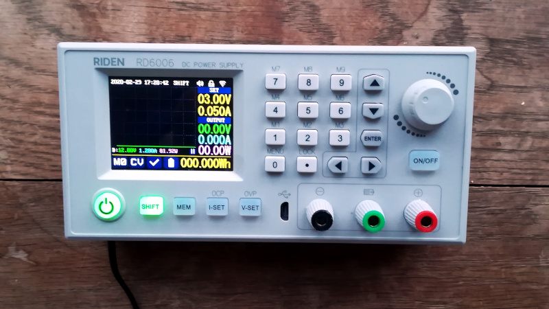
This power supply has ten programmable presets (voltage/current settings) and can be controlled remotely via USB or WiFi.
The following snippet of python shows how simple it is to control this power supply.
from rd6006 import RD6006
power = RD6006('/dev/ttyUSB0')
# Enable power
power.enable = 1
# Disable power
power.enable = 0
Using the version that connects to WiFi, a mobile app can control the power supply remotely. The ability to programmatically control our power source will come in handy in case we need run repeated tests where we cycle power to the target. There is an example use case for this in part three.
Multimeter
A multimeter is a must-have for any hardware lab. Multimeters perform electronic measurements such as:
- Voltage (AC and DC)
- Current
- Resistance
- Continuity
Multimeters vary widely in cost and features, but multiple cost-effective multimeters are available for our work and many hobbyists. Some factors to be aware of when selecting a multimeter include
- What will the meter be used for?
- Manual or auto-ranging?
- What measurements are available?
For our purposes, we will not need a very expensive multimeter as we will mainly be measuring continuity, voltage, and resistance. It's important to note that some cheap multimeters take more time to measure than others, resulting in a bit of lag. This one that I usually recommend for beginners avoids this problem.
Logic Analyzer
Another commonly used tool in the hardware hackers toolbox is the Logic Analyzer. Logic Analyzers capture and display electronic signals in digital circuits. Logic analyzers can also decode and analyze these signals, converting a digital data stream into a more human-readable format.

While I am a big fan of the Salaea logic analyzers, these are relatively expensive for most hobbyists. Therefore, I will use a low-cost fxXXX series logic analyzer for this series. One can purchase these analyzers from eBay or Amazon at a reasonably low price. The software that we will use with these analyzers will be the PulseView software suite.

When choosing a logic analyzer, there are several factors to consider, which I have outlined in the table below.
| Factor | Definition |
|---|---|
| Channel Count | How many channels you can capture at one |
| Sample Rate | How many measurements are taken per second, typically you want to be sampling at 4x your target speed |
| Voltage Levels | Defines the voltage levels supported by the analyzer; this will determine the threshold for your input measurements |
For the targets we will be looking at, a sample rate of 24MHz will suffice. However, for professional use, I would recommend a Saleae or another logic analyzer capable of at least 100MHz.
These Logic Analyzers are supported by the PulseView / Sigrok software, which we will be using throughout these posts.
Breadboard/Jumper Wires
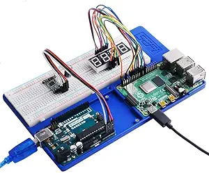
We will need a way to connect our Raspberry Pi to our various targets; for this, we will typically use a breadboard. Breadboards allow us to prototype electronic circuits without the need for soldering. When working with the Raspberry Pi, I am a big fan of the case/breadboard combination shown below:
Soldering Station
There will be some situations where one might need to solder to our targets. For example, sometimes we will need to solder directly to components to take measurements/interface with them, while other times we need to remove parts altogether.
The proper soldering iron for your lab will depend on several factors:
- What will you be soldering?
- Circuit Boards
- Automotive Components
- Home Wiring
- How much desk/workbench space do you have available?
- Do you need a hot air rework station?
- Will you be removing/adding SMD/SMT components?
If you are looking for a low-cost station, I recommend this one. It's temperature can range from 392 to 896 and can be controlled via the station. If you are going to be doing SMD rework and removing BGA devices, you will want to choose a station with hot air rework capabilities.
This video can provide more information about choosing an appropriate workstation.
Other Hardware Tools
Thus far, I have listed only the bare minimum for what I will be using for the upcoming blog series. However, many other tools and components can be helpful in your hardware lab, and I've listed them below:
- Silicon Mat
- Provides a safe surface platform for probing devices/soldering
- Microscope
- Resing small part numbers and investigating printed circuit boards
- FTDI Breakout
- Hardware multitool with widespread support across various programming languages
- Oscilloscope
- Used to view analog signals, good for investigating mysterious/troublesome data lines that aren't working as expected, also used to collect power traces for differential power analysis and voltage glitching
- Guide to choosing an oscilloscope
- ChipWhisperer
- Used to perform voltage glitching and side-channel analysis. NewAE provides an excellent series of tutorials and examples as well.
As you continue to research and analyze more targets, your hardware needs will grow. This article outlines the essential components needed to follow this specific blog series.
Software Tools
Remember that hardware is frequently only the first hurdle in your reverse engineering process. More often than not, we are reverse engineering at the hardware level to get increased access to software-level components. We will use several software tools throughout this series, highlighting the core tools below.
Ghidra
Those of you familiar with my background know that Ghidra has quickly become a go-to tool for me in the realm of software reversing.
Ghidra is an SRE (software reverse engineering) suite of tools developed by NSA. If you are familiar with IDA-Pro, r2, or Binary Ninja, you are already likely familiar with Ghidra. We can use any tools mentioned above to reverse engineer this firmware image. Still, I am choosing Ghidra as it is open source and has a relatively robust and well-documented API for scripting and analyzing binaries. Ghidra is also growing with contributions from the community (most notably for me was the addition of the Infineon Tricore architecture to the list of supported CPUs).
The benefits of using Ghidra are many:
- It is entirely open-source and free
- Large library of supported architecture
- Disassembly and decompilation tools for all supported architectures
- Java/Python API for extending analysis/plugin development
When we review firmware images throughout this series, we will use Ghidra. In addition, throughout this series, we will learn how to:
- Add memory regions to firmware images
- Augment the auto-analysis with custom ghidra extensions
- Emulate Ghidra's PCode to understand firmware behavior better
I have written a blog post here about setting up a development environment for developing Ghidra modules and scripts. We will be using this environment when we review the firmware images that we extract from our targets.
Binwalk
Before we load a binary or firmware image into Ghidra, we need to answer a few basic questions:
- What architecture was this software written for?
- Is this image compressed or encrypted?
- Are there additional files or filesystems embedded in this firmware image?
binwalk can help us answer almost all of these questions, or at the very least set us on the right path to finding the answers.
Binwalk is a tool that examines a binary file and searches for predefined file formats. Some of these formats include:
- Executable formats for multiple operating systems
- Filesystem images
- Multimedia files
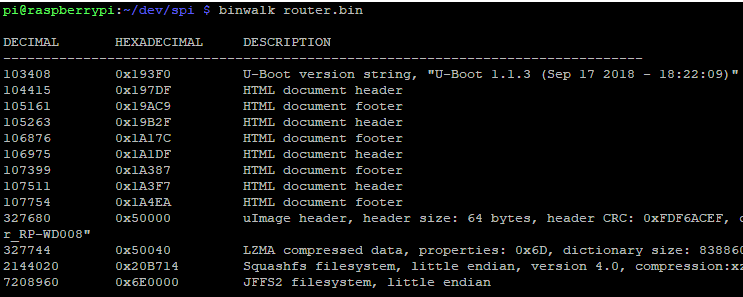
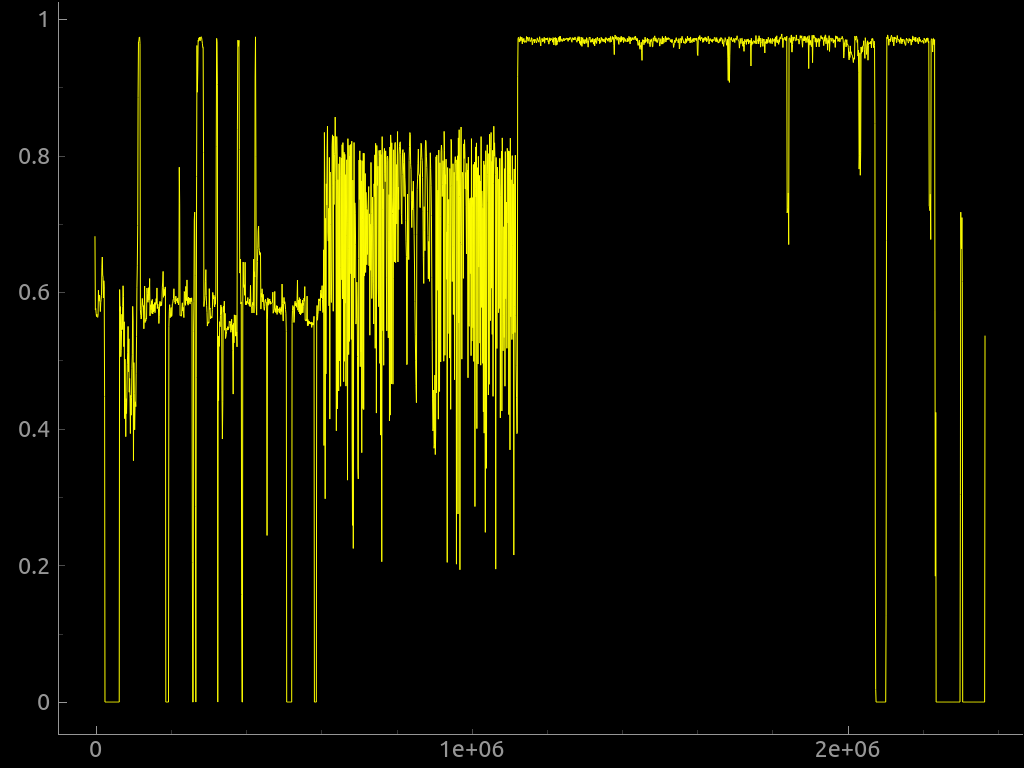
Binwalk can also generate an entropy graph, which is extremely useful when determining if a firmware image is encrypted or compressed. When we extract a firmware image from a target, we will perform our initial analysis using binwalk. The output from binwalk will help us determine the next steps we need to make to extract the data of interest.
Kaitai Struct
Once we understand the structure of a given binary or firmware image, we may need to write a parser to extract the data of interest. Kaitai struct has quickly become my go-to tool for writing custom binary parsing tools.
From the README:
Kaitai Struct is a declarative language used for describing various binary data structures laid out in files or memory: i.e., binary file formats, network stream packet formats, etc.
The main idea is that a particular format is described in Kaitai Struct language only once and then can be compiled into source files in one of the supported programming languages. In addition, these modules will include a generated code for a parser that can read described data structure from a file/stream and give access to it in an easy-to-comprehend API.
We can use Kaitai struct to write a template for a binary file and using that template, Kaitai will generate a parsing library for us. This tool is incredibly time-saving, and multiple output languages are supported. Below are some example applications of Kaitai Struct that I have written for a custom filesystem implemented by the ePOS RTOS.
Kaitai also features a web-based IDE that can be run locally, see an example in the screenshot below:

You can learn more about Kaitai and download the relevant tools from kaitai.io
Pulseview / SigRok
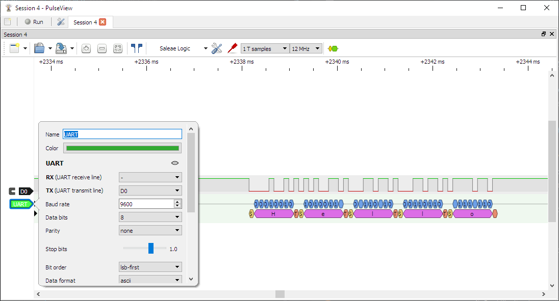
Pulseview is the frontend software for Sigrok. We will be using this to analyze and view the data that we capture with our logic analyzer. In addition, Pulseview will apply various protocol decoders to the traffic we capture, allowing us to derive more meaning from the captures and make the output of our captures more human-readable. For example, using the UART decoder, we can go from this:
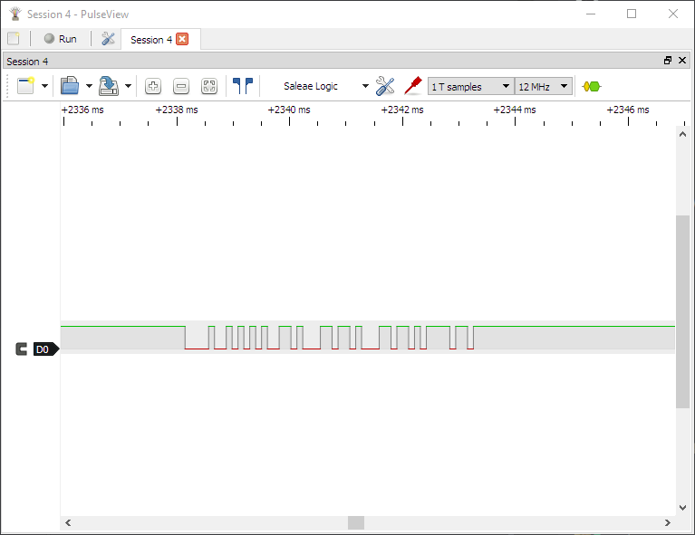
to this:
We can also export this data for further analysis, write our plugins and even programmatically script how information is collected. Pulseview and sigrok are also wholly open-source and have many compatible devices, including some versions of the Saleae Logic analyzers. You can download the Pulseview software here
Tools: Conclusion
The tools listed here are just some of the tools needed to reverse engineer embedded systems/firmware. I have listed the ones that we will commonly use throughout this series and will update them at the end of the series with things missed for future readers. Note that I left out stuff like hex and text editors, primarily because everyone has a personal preference for editors. If any tools are missing or that you think should be included, please don't hesitate to reach out to me and let me know!
Next, let's talk about how this series will be structured.
Series Outline
This series aims to review the fundamentals of embedded system reverse engineering from both a hardware and software perspective. In the post outline below, the posts aren't strictly separated into hardware vs. software. I chose not to separate these in this series because neither hardware nor software reverse engineering can exist in isolation for our targets. For example - we need to understand how the UART works to write our custom Deptcharge module to extract the firmware. We also need to know how the hardware peripherals are accessed to understand better what the binaries are doing when analyzing them in Ghidra. For this reason, I've decided to list the planned posts below. Throughout this series, we will cover:
- Part 1: Tools / Series Overview
- Part 2: Building a Development Environment for Ghidra
- Part 3: Firmware Extraction via UART, UBoot and USB
- Part 4: Firmware Extraction via SPI
- Part 5: I2C and Parallel Flash Extraction
- Part 6: PCode Emulation
- Part 7: JTAG Overview and Applications
Each post will focus on the fundamentals of embedded systems reverse engineering. I selected these targets to showcase the various protocols and necessary Ghidra modifications to analyze their firmware correctly.
Post Structure
Each post in this series will begin with an overview describing the target and what we hope to learn. We will then outline the objectives of the post, relating to the reader in detail what our specific goals are with this target.
Each post will end with a link to a GitHub repository where all materials for a given target will be accessible. The repositories, of course, will not contain firmware images or any proprietary or confidential data - only the tools required to replicate the work described.
Conclusion
This post outlined a series of posts for 2022 whose goal is to serve as a roadmap for both hardware and software engineers. If you're interested in learning more about this and would like to take a course, check the availability here. if you want to get updated when new posts come out as well as my quarterly newsletter - sign up here
Thank you for your time, and if you have any feedback, please don't hesitate to contact me through Twitter or email!